General Setup description
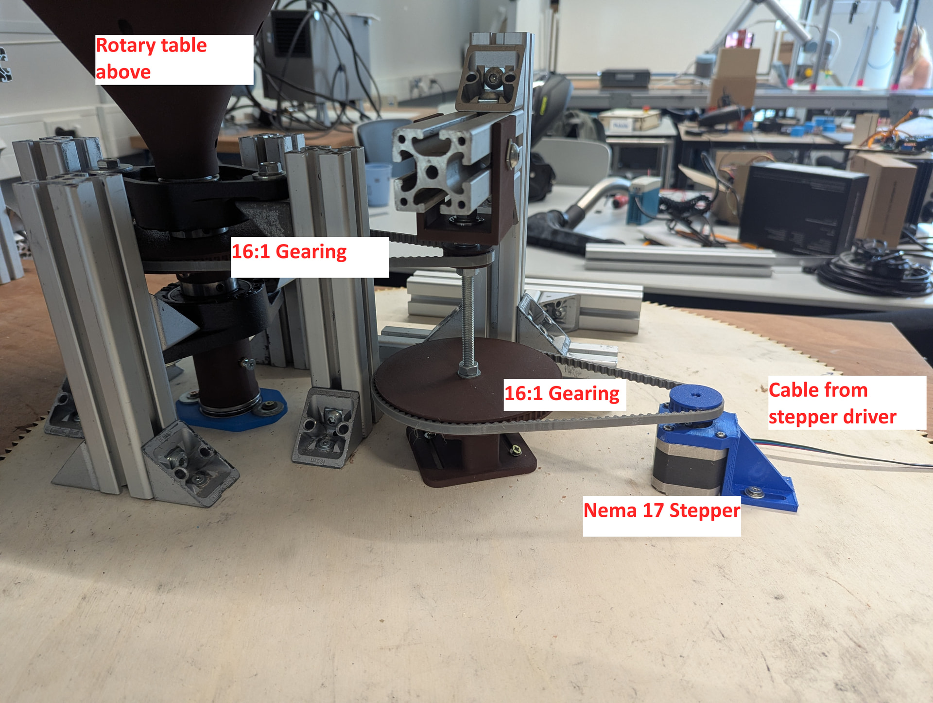
For our project we had a stepper motor controlled by an Arduino Uno R3, driving our geared rotary table. Perhaps you can use this knowledge to your own project.
We will look at the following:
- Electrical / wiring setup of a stepper, arduino and stepper driver
- Mechanical setup of a gearing (using pulleys and belts) driven by the stepper
- Coding of the arduino to communicate to the driver and control the stepper
The setup was as shown below:
Electrical connections
We are using a nema 17 stepper motor and a DM542 driver.
Pin connections from stepper driver to Nema 17 are:
| Driver side | Stepper side |
|---|---|
| A+ | Black |
| A- | Green |
| B+ | Blue |
| B- | Red |
Connections from the Uno R3 to the driver:
| Driver side | Arduino Uno side |
|---|---|
| PUL+ | Pin 9 |
| PUL- | GND |
| DIR+ | Pin 8 |
| DIR- | GND |
Furthermore, please note that the stepper driver needs an external power supply, we are using 24VDC which is connected to V+ and GND on the stepper driver. You can find industrial PSU’s in the lab, they look like this:
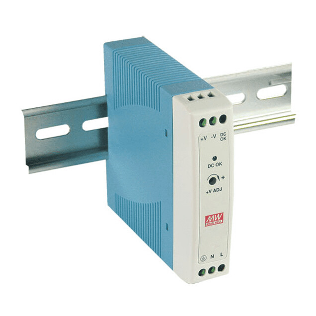
BE CAREFUL CONNECTING THE ABOVE TYPE PSU AS THEY TAKE IN EXPOSED 240VAC LEADS WHICH ARE DANGEROUS. ASK QUINTEN FROM THE WORKSHOP FOR TIPS HOW TO DO THIS.
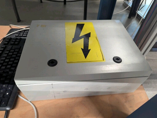
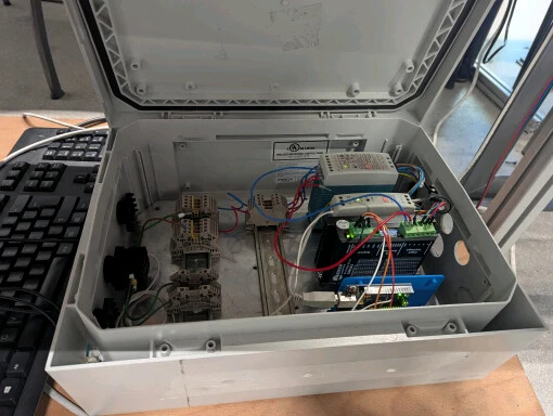
We put our setup in an electrical cabinet with everything mounted to DIN rails, for a secure and safe setup:
Mechanical / gearing considerations
You need to consider that the torque of a stepper is quite limited. They are powerful for their size, but at the same time they are small. Therefore, you should plan your gearing according to how much inertia your mechanical setup needs. Our table ended up being quite heavy, but we didn’t need any speed at all, so we chose a 32:1 total gearing ratio. Remember the stepper can also be coded to reduce its speed of course, it just doesn’t equal more torque though. Only the gearing can increase that if you aren’t able to choose another motor.
Coding of the Arduino for control of the driver and stepper
Arduino Stepper Code.txt (8.8 KB)
We used the above code in our project. Adjust it however you like.
This code allows for serial input in the serial monitor, within the arduino IDE. It looks like this:
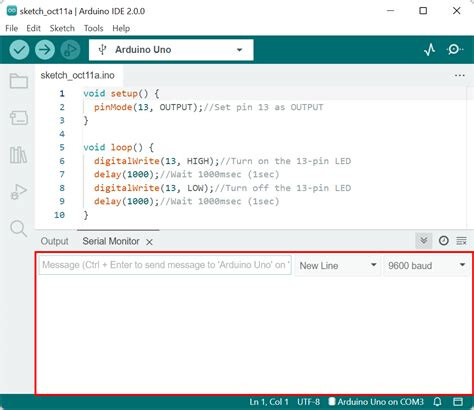
There you can send commands via USB to the Arduino, e.g. “DEG: 360” or “ROTATE” to do the requested degrees of rotation. Check out the code for more features, or upload it to an AI to investigate it and make changes as you see fit.