How-to: Communicating between a Doosan robot and a microcontroller using a transistor
Goal
This how-to explains how to send a simple digital signal between a microcontroller and a Doosan robot toolhead using a transistor.
In our project, we needed a Doosan M1013 robot to communicate with a microcontroller. The microcontroller controlled sensors, servos and gripper logic, while the robot needed a simple digital signal to continue or stop its program.
The problem is that the Doosan toolhead uses 24V digital I/O, while an ESP32 or Arduino uses 3.3V or 5V logic. These cannot be connected directly.
This how-to shows a solution using a transistor.
We used:
- Doosan M1013 robot
- ESP32 microcontroller
- Doosan tool digital input
- 2N2222 NPN transistor
- Resistors
Why a transistor is needed
A Doosan digital input expects a 24V signal.
A microcontroller output pin gives only 3.3V or 5V and cannot safely drive the robot input directly.
The transistor works as a small electronic switch:
- Microcontroller output LOW → transistor off
- Microcontroller output HIGH → transistor on
- Transistor off → Doosan input is pulled to 24V
- Transistor on → Doosan input is pulled to GND
This means the signal is inverted.
Wiring
The Doosan digital input point is pulled up to 24V using a resistor. The transistor can pull this point down to GND.
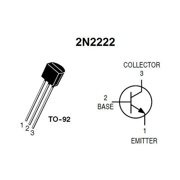
Connections:
collector → Doosan digital input
emitter → Doosan GND
base → microcontroller output through a resistor
Doosan GND → microcontroller GND
Doosan +24V → pull-up resistor → Doosan digital input
Do not connect the Doosan digital input directly to +24V without a resistor in this transistor setup.
Resistor values
Recommended values:
Pull-up from +24V to Doosan DI: around 10k to 15k
Base resistor from ESP32/Arduino output to 2N2222 base: around 10k to 39k
This can be used as the pull-up from Doosan +24V to the Doosan digital input.
Logic
The signal is inverted:
Microcontroller output LOW → transistor off → Doosan DI HIGH
Microcontroller output HIGH → transistor on → Doosan DI LOW
So in the robot software or microcontroller software, the logic may need to be inverted.
ESP32 / Arduino test code
This example toggles the output every 3 seconds.
#include <Arduino.h>

const int DOOSAN_SIGNAL_PIN = 15;

void setup()
{
    Serial.begin(115200);

    pinMode(DOOSAN_SIGNAL_PIN, OUTPUT);
    digitalWrite(DOOSAN_SIGNAL_PIN, LOW);
}

void loop()
{
    Serial.println("output LOW -> Doosan DI  HIGH");
    digitalWrite(DOOSAN_SIGNAL_PIN, LOW);
    delay(3000);

    Serial.println("output HIGH -> Doosan DI LOW");
    digitalWrite(DOOSAN_SIGNAL_PIN, HIGH);
    delay(3000);
}
Testing with a multimeter
Before connecting the Doosan digital input, test the collector point.
Measure between:
Red probe   -> collector / Doosan DI point
Black probe -> GND
Expected result:
Microcontroller output LOW  -> about 24V
Microcontroller output HIGH -> about 0V
If this works, the signal is safe to connect to the Doosan digital input.
Reading the input on the Doosan side
In C++ with DRFL, the tool digital input can be read with get_tool_digital_input.
Example:
int input_value = robot.get_tool_digital_input(
    static_cast<GPIO_TOOL_DIGITAL_INDEX>(3)
);

if (input_value == 1)
{
    std::cout << "Doosan input is HIGH" << std::endl;
}
else if (input_value == 0)
{
    std::cout << "Doosan input is LOW" << std::endl;
}
else
{
    std::cout << "Error reading Doosan input" << std::endl;
}