Overview
Trying to connect a sensor to your Doosan PLC, but it doesn’t seem to work?
It could be because the sensor’s signal output is too weak for the PLC to detect.
You can use a microcontroller (like an Arduino) to detect the signal and send it to your PLC or script.
In the following steps, I’ll explain how to integrate this setup with your Python code.
Step 1: Wiring the Sensor Correctly
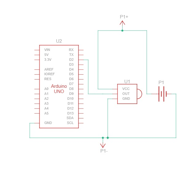
- Connect the signal output of the sensor to a digital input pin on the Arduino.
- Use a breadboard to connect the V+ and GND to the sensor.
(Make sure to read the documentation for the sensor to check the appropriate voltage and how it should be connected.) - The diagram below shows how our Photoelectric sensor is connected to the Arduino:
Fig. 1 — Wiring diagram of the Photoelectric sensor to an Arduino.
Step 2: Read the Digital Input Pin on the Arduino Using Code
if (digitalRead(SENSOR_PIN) == LOW) {
    count++;
    Serial.print("Count: ");
    Serial.println(count);
}
This code checks if the sensor is triggered and prints a counter value to the Serial Monitor.
Step 3: Connect Arduino to the Python Script
- First, import the serial library:
import serial
- Connect to the Arduino by using this line (edit the baud rate and COM port to match your setup):
arduino = serial.Serial('COM11', 115200, timeout=1) # Connect to Arduino
Step 4: Read Serial Data from Arduino in Python
Use the following code snippet in your Python script:
if arduino.in_waiting > 0:
    count_value = arduino.readline().decode().strip()
    print("Count from Arduino:", count_value)
This reads the serial data coming from the Arduino and prints it in the terminal.
Step 5: Test your sensor and eliminate false positives
Once everything is wired and coded correctly, it’s time to test your setup in a real working environment. Sensors can behave differently depending on lighting, motion, vibrations, or electrical noise — especially in industrial settings.
Steps to follow:
- Run the sensor with your Arduino connected and observe the serial output on your computer.
- Trigger the sensor intentionally (e.g., by placing an object in front of it) and see if the Arduino consistently registers the event.
- Look out for false triggers, which may appear as random count increases or inconsistent readings — even when the sensor hasn’t actually been triggered.
Tips to reduce false positives:
- Use debounce logic in your Arduino code, especially for mechanical switches or IR sensors:
if (digitalRead(SENSOR_PIN) == LOW && millis() - lastTriggerTime > 200) {
    count++;
    lastTriggerTime = millis();
    Serial.println(count);
}
- Do a simple stability check in your Arduino Code:
bool stableLow = true;
for (int i = 0; i < 5; i++) {
    if (digitalRead(SENSOR_PIN) != LOW) {
        stableLow = false;
        break;
    }
    delay(2);  // 2ms delay between checks (10ms total)
}

if (stableLow) {
    count++;
    Serial.print("Count: ");
    Serial.println(count);
}
If the steps above don’t solve the issue, here are a few extra things you can check:
- Add a small delay between readings to reduce noise or bouncing.
- Use a capacitor or apply a software filter (for analog sensors) to smooth out unstable signals.
- Physically isolate the sensor from vibration or electrical noise sources.
- Use shielded or twisted-pair cables for longer wires, especially if they run near motors or high-voltage lines.
- Double-check sensor specs and voltage levels to ensure compatibility with the Arduino and the sensor’s required power.