How to design an air-cushion track
In the world of industrial automation, air-cushion tracks are used often. This makes for a nearly frictionless way of transporting objects. Such air-cushion track can be made in one of two ways, an air-rail on either side of the object, or an direct air-pushing system. This how-to will focus on the latter and will give a guide with the important things to focus on while developing an air-cushion.
Air-cushion tracks are mostly known by the implemention on the very popular game air-hockey.
An example for the use of such track in industrial automation is the following picture:
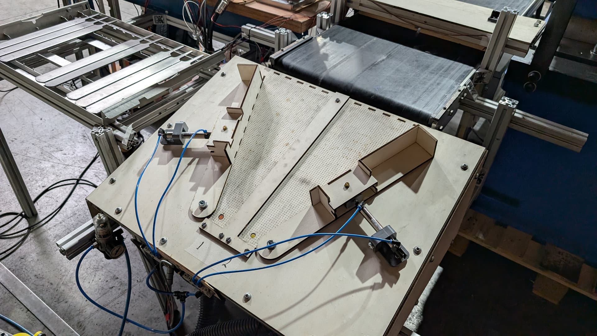
In this picture an air-cushion track is seen. This one works for catching viles that are exiting the conveyor belt. The viles have teeth that would normally stop it from sliding downwards, however the air-cushion eliminates most of the friction between the vile and the surface. This causes the vile to slide into the end of the funnel on either side effortlessly.
How to design the air-cushion
There are a few things to take into account when designing an air-cushion.
- Air Flow >>> Air pressure.
— The cushion doesn’t need a lot of pressure to create lift-off force, however you need enough air-flowrate to lift the object. For this project a blower was chosen, however a large fan on the bottom would probably also have suffided. - Hole size and hole distance
— The exit flow of air can be regulated by a numerous of factors. The diameters of the holes is very important. Usually the hole can by quite small. For this project 0.75mm holes were used. equilly as important is the distance of the holes. That decides how many holes are used on a surface. For this project a distance of 5mm was used. - Air supply style
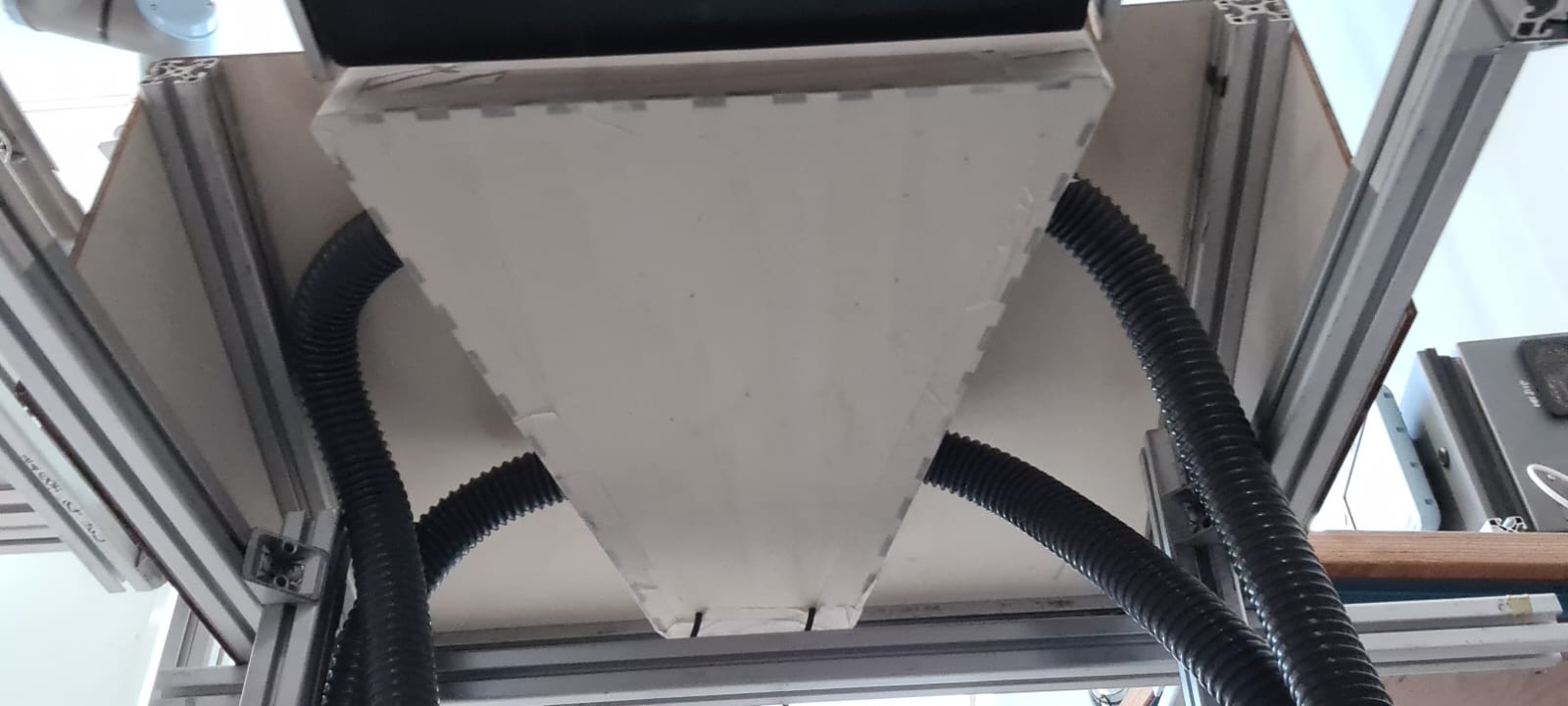
— Another important thing to decide is the air supply. When supplying air with a blower it must be made sure that airsupply is distributed evenly into the air-pocket under the holes. If air is blown in from one side, the other side would get overpressure and that side would ge overpressure. Thats why for that project a splitter was 3d-printed and mounted on the blowing, allowing four tubes to blow air into the pocket on all four corners evenly. See the picture below:
Calculating flow and holes
It is possible to completely calculate what the necessary values need to be for:
- Q (Air flowrate)
- A (total surface of all holes)
- D (diameter of the holes)
- d (distance between the holes)
- P (required pressure under the object)
For most small SMR projects this will not be necessery and it will be faster and easier to experiment with the guides that have been given in this how-to. However if you were to implement such system professionally, these are the formulas needed to calculate these values:
𝑃 = (𝑚𝑔)/𝐴
P = required pressure under the object (in Pascals, Pa)
m = mass of the object (kg)
g = gravitational acceleration (9.81 m/s²)
A = area of the bottom of the object (m²)
Q = C*A √(2P/ρ)**
To decide what the holes diameter and distance is, is must be made so that the total surface of the object has enough holes balanced to the pressure needed to lift the object.