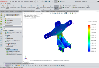
If you want to perform a stress analysis on a design created in SolidWorks, but aren’t sure how to get started, here is a step-by-step guide for performing a basic stress analysis on a model.
Step 1: Enable the Simulation Add-In
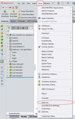
- Go to Tools > Add-Ins.
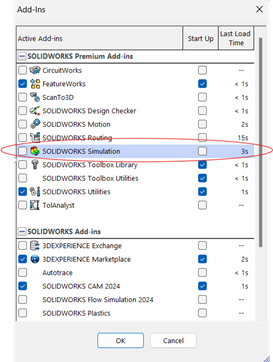
- Check the box next to SolidWorks Simulation.
- This will add the Simulation tab to your SolidWorks interface.
Step 2: Set Up a New Simulation Study
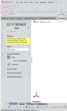
- In the Simulation tab, click New Study.
- Select the type of analysis; for stress analysis, choose Static.
- Name the study and click OK. This will create a new Simulation study tab.
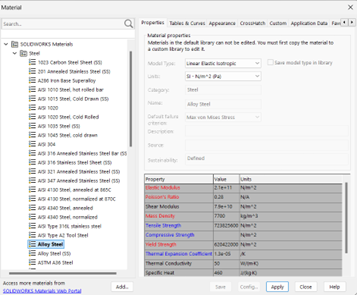
Step 3: Apply material
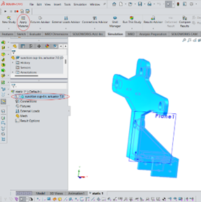
- Select the part.
- In the Simulation tab, click apply material.
- Select the material that your part will be made of.
Step 4: Apply Fixtures
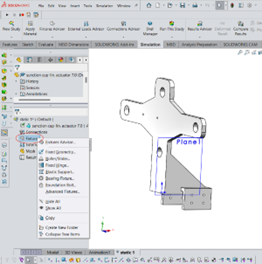
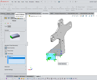
- Right-click on Fixtures in the Simulation tree and choose the appropriate fixture type (e.g., Fixed Geometry, Roller/Slider).
- Click the faces where you want to apply these constraints. Fixtures prevent movement and rotation in specified directions.
Step 5: Apply External Loads
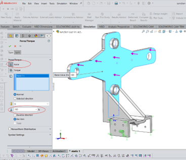
- Right-click on External Loads in the Simulation tree and select the type of load.
- Select the surfaces or edges where the load will be applied.
- Specify the magnitude and direction of the load.
Step 6: Mesh the Model (if needed)
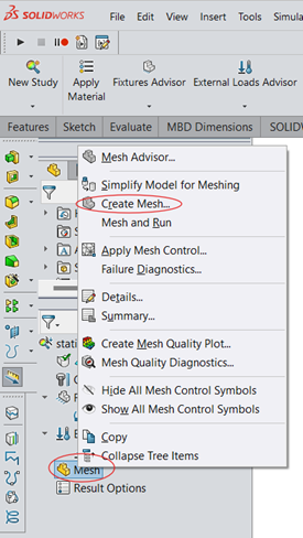
- Right-click on Mesh in the Simulation tree and select Create Mesh.
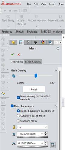
- Adjust the mesh density as needed. A finer mesh usually provides more accurate results but increases computation time.
- Click OK to generate the mesh.
Step 7: Run the Analysis
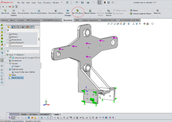
- Once the fixtures, loads, and mesh are set, click Run in the toolbar to start the simulation.
Step 8: Review the Results
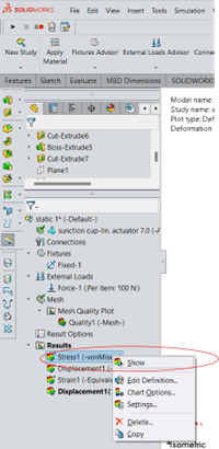
- To view stress results, right-click on stress and select show plot.
