This how-to explains the usage of SolidWorks Design Study to evaluate how variations in geometry, material, or loading affect the bending behavior of components, based on tests from a real machine development project. The tutorials found online are using simple 3D models, but this how-to is going to focus on oddly-shaped components. The use case in question is a galvanized steel thimble used in marine logistics that needs to be pried open. When automating a system that uses manual labor, estimating forces applied on certain components might present certain risks, especially when the deformation applied implies a big force.
-
Prerequisites:
Before you begin, ensure you have:- SolidWorks Education (Simulation add-in enabled)
- A 3D model of the component
- SolidWorks Simulation setup for a static or nonlinear study
- Basic knowledge of setting materials, fixtures, and loads
-
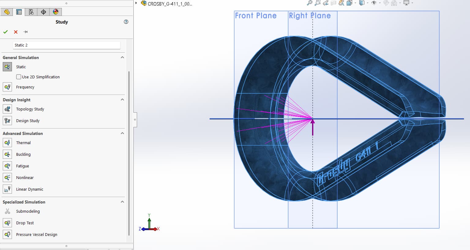
Setting up the simulation:
- Simulation > Study > New Study
- Choose static or nonlinear depending on the material behaviour
-
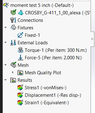
Set up Design Study
- Choose the proper material for the 3D model. This can bee dependent on the actual study you are trying to achieve.
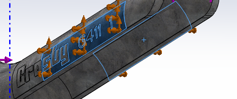
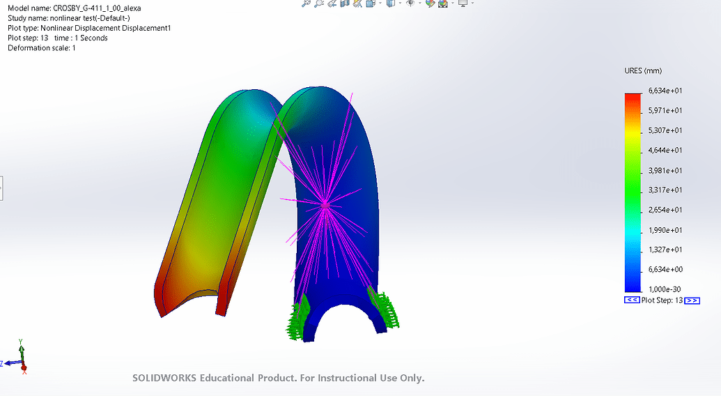
- Set up fixtures depending on how is the object fixed into place. The example used is a thimble fixed into place by a mechanical vice.
- Apply the loads depending on the known parameters. The design study feature in SolidWorks allows you to apply displacement (if you know the distance that you want to achieve), force (if the force was measured accurately) or torque (if the object is being twisted). Other external loads can be taken into consideration as well depending on the design study you want to make.
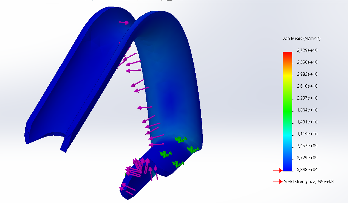
- After you apply external loads, you need to mesh the model and run the study.
- Choose the proper material for the 3D model. This can bee dependent on the actual study you are trying to achieve.