How to use Mechanical Mates (Hinge)
In this minor SolidWorks is usually used to model the hardware setup of the project, whether it is for an end-effector on a cobot or for an entire self-made setup. When you make an assembly from parts in SolidWorks, you use mates to connect them. When you only use standard mates, the assembly will become static. Mechanical mates can give you a dynamic assembly where you can move parts within given limitations. Moving assemblies can give you better insight into your design before building it.
Use cases
• Modelling the movement (and restrictions) of a cobot
• Trying out different stations in an assembly line
• Testing standard movements and constraints like a hinge, gear, rack pinion, universal joint
Example
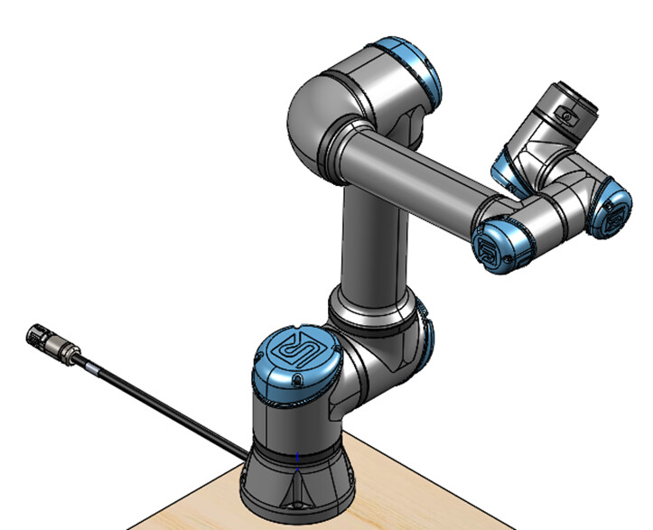
As an example, the hinge mate will be used on the base of a UR5e cobot to demonstrate one the options
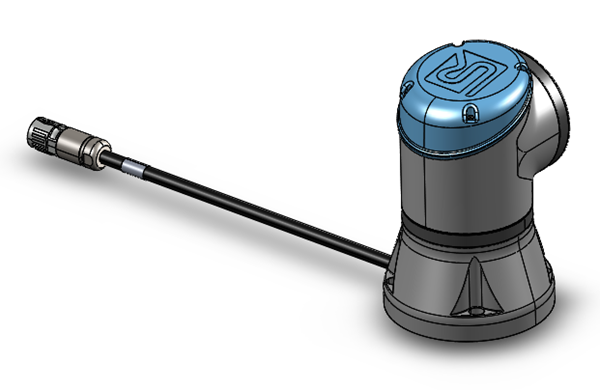
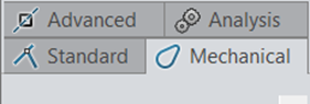
The base connection consists of the mounted base and link 1. To use the hinge mate, go to the mechanical tab of mate
You need to appoint a few connections: concentric, coincident, angle limits
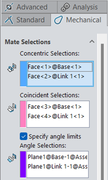
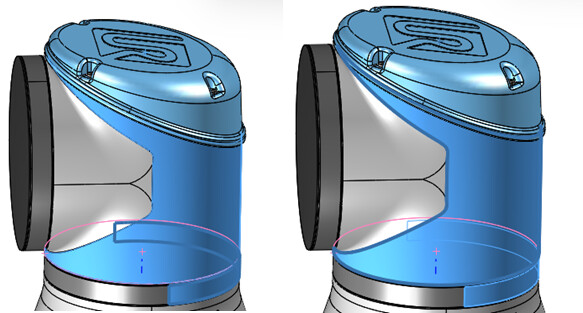
1. Concentric selections
Select the round shapes that you want to use as hinges, here for example the housing of link 1 and the end of the base.
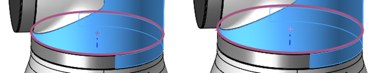
2. Coincident selections
The top surface/edge of the base and the bottom surface/edge of link 1 are used to coincide.
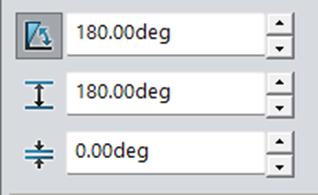
3. Specify angle limits
If you don’t want the objects to rotate freely, you can add angle limits. This will create desired limitations to movement.
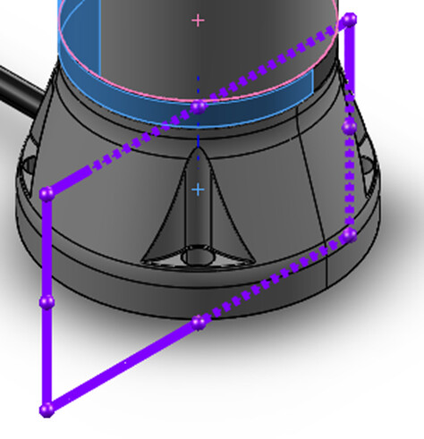
In the case of the cobot, there are no flat surfaces to select so reference planes have to be added to the parts (so not in the assembly) These reference surfaces can be linked to each other. Try out the angles because it is not always clear what the alignment is like
4. Result
When repeated for each link, a realistic assembly of the cobot is created that can move within its limitations