How to make smarter parts in inventor?
To make smarter parts this module will use the iLogic function in Autodesk Inventor. The functions used are also similarly available in other CAD software such as Solidworks. This module will be divided into 3 parts, the first part will go over parameters and simple equations to make modular smart parts. The second part will show a few simple functions which can be useful to interact with parts. The third part will go deeper into the inventor objects to set or get information from parts which can be useful for external use such as in this topic about making AS code out of Inventor files.
Parameters
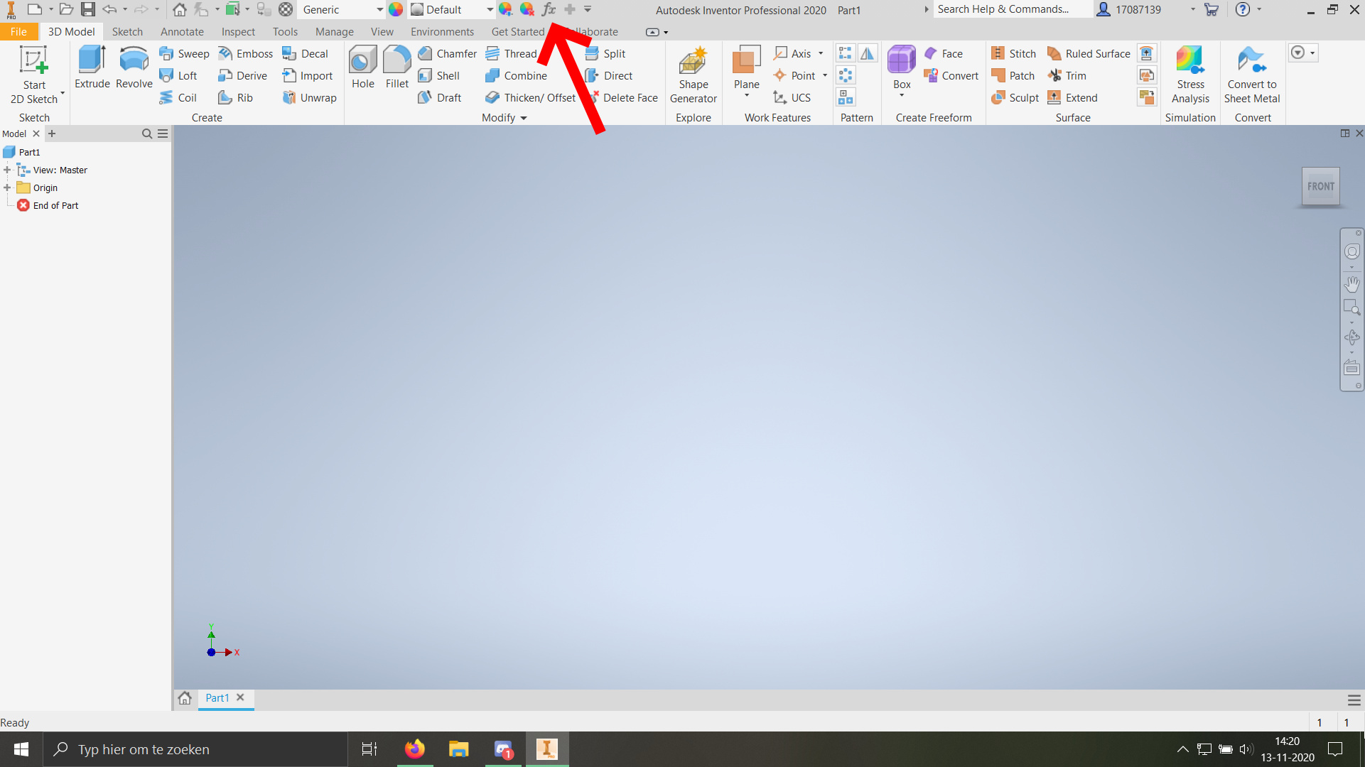
To get started with parameters it is useful to know where to find where Inventor stores its parameters. To open the parameter page the fx button on the top of the screen can be pressed.
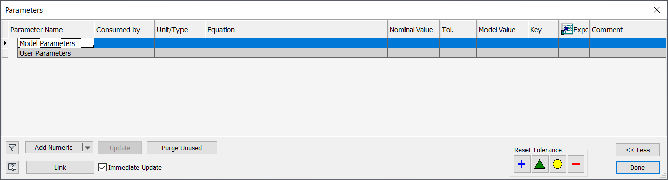
Depending on the part there might already be automatically generated parameters, otherwise, the parameters list should be empty and look like this:
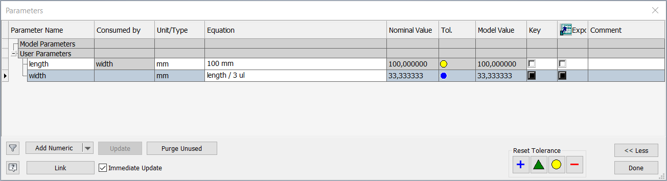
By pressing “Add Numeric” in the bottom left corner a parameter can be added. Let’s start by creating a parameter called “length”, with Unit/Type set to mm (default) and value of 100,0 mm. If this is performed correctly the parameter pop-up window will now show the new parameter under “User Parameters”, which makes sense since the parameter is created by the user. When the first parameter is made successfully a second one can be made. Let’s call this one “width”, set the Unit/Type to mm again. For the value, we can do something special in this case. Instead of filling in a fixed value, we can fill in “length / 3 ul” (the “ul” part will be autocompleted and stands for unitless). This is super useful because the width will now always be a third of the length. If everything so far is done correctly the pop-up window should now look like this and can be closed again:
Now, let’s use the parameters just created! This will be demonstrated in a new 2D sketch. In sketch mode create a rectangle with undefined side lengths. Now use the Dimension tool to add dimensions to the sides, but instead of filling in a value give up “length” and “width”. This will result in the following sketch:
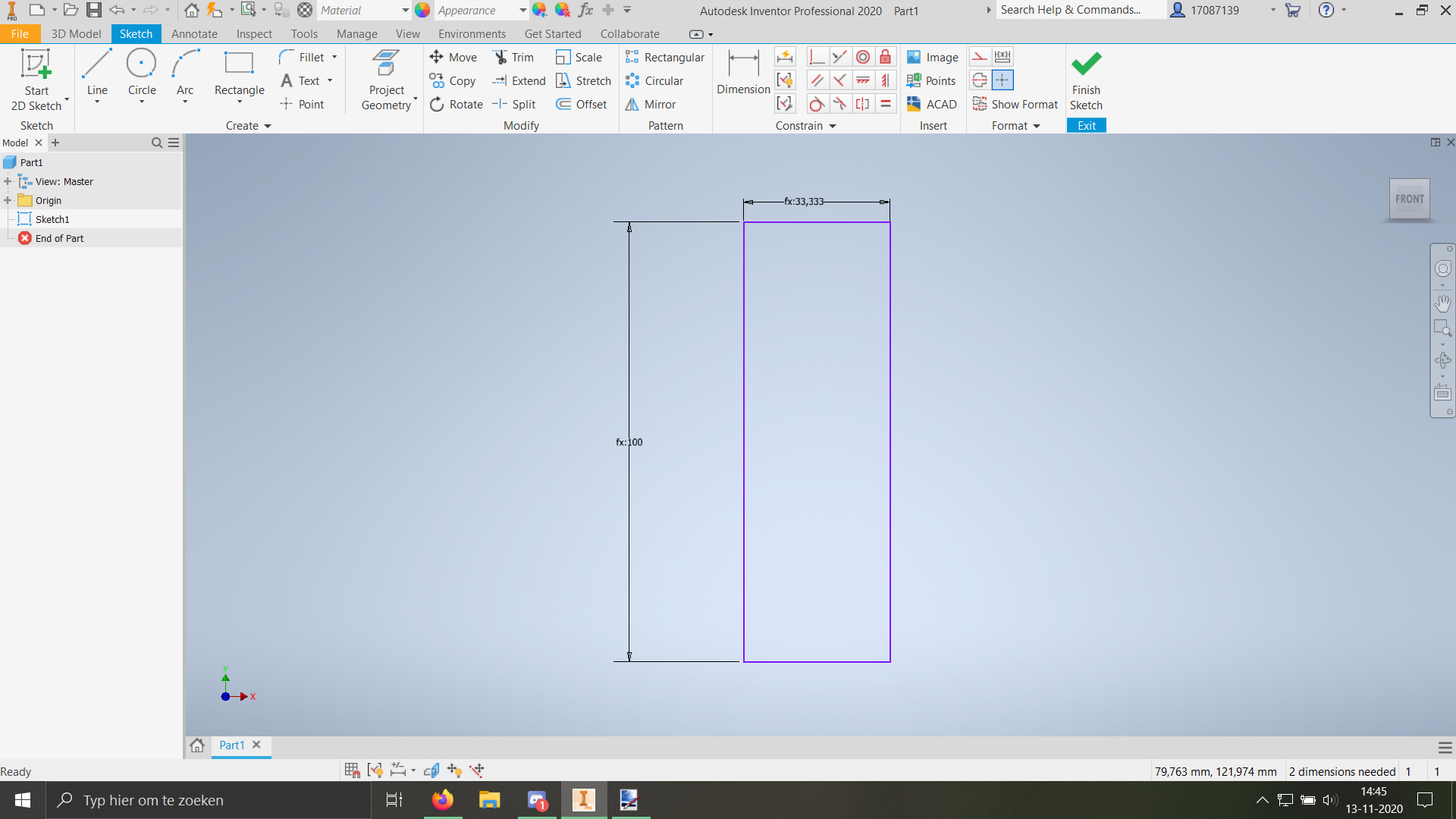
As can be seen, the result is a rectangle which width is equal to 1/3 of the length. Now exit sketch mode and open the fx menu again. When you change the length value you can see how the width also changes and will stay 1/3th of the length as specified. You can also see that inventor automatically created 2 Model Parameters, those are the parameters the model is based on (in this case d0 and d1 are the height and width of the rectangle in the sketch)
In the above-shown example, the parameters are used on a sketch, but custom parameters can also be used on extrusion lengths, pattern iterations, fillet sizes, constraints (in assembly’s) and for way more!
Using iLogic to interact with parameters
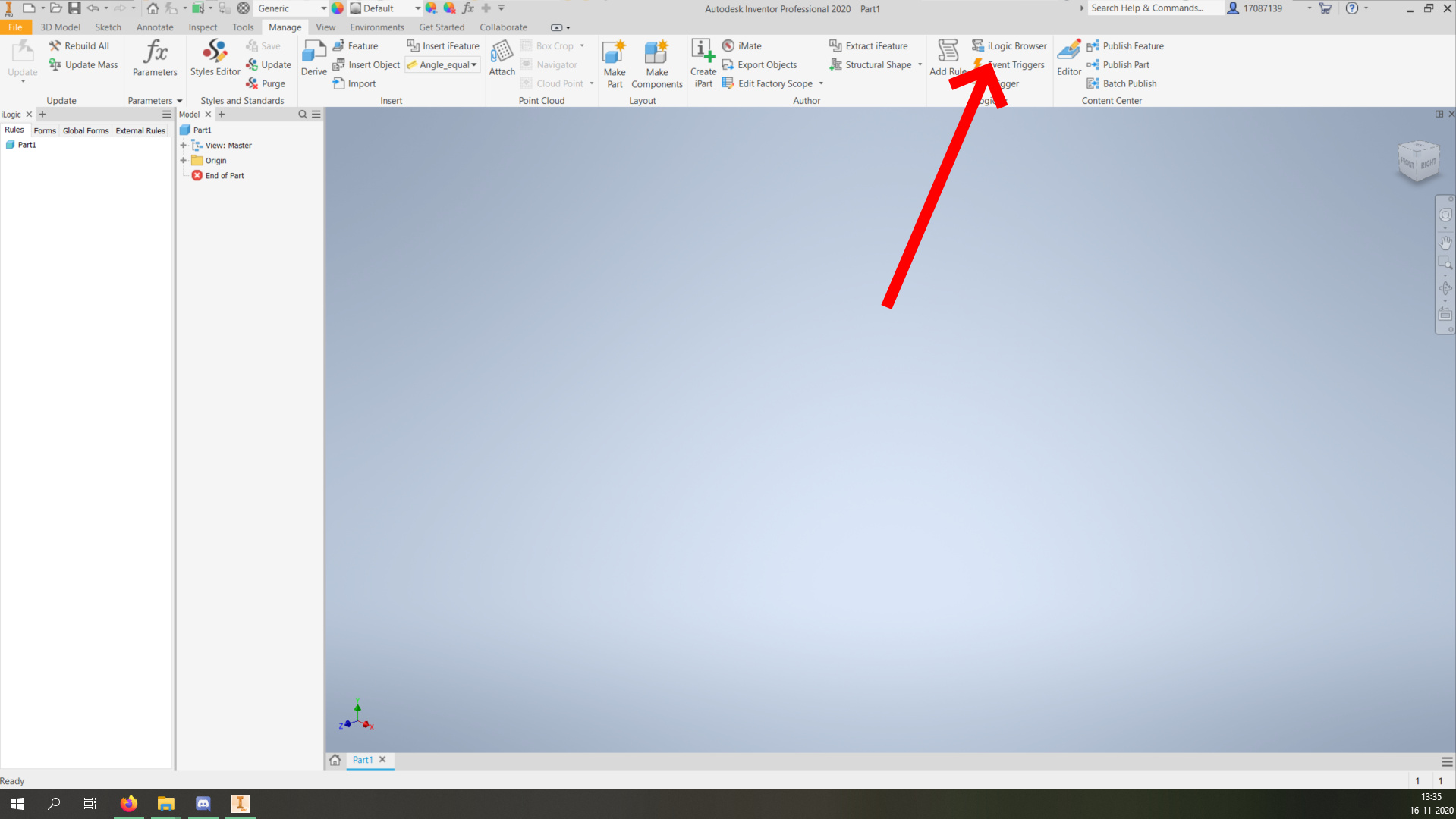
often a simple function is not good enough to make a part do the things you desire. For this iLogic scripts can be used. iLogic is a programming interface inside Inventor where you can program in VB.net. To get started with this we will start a new file in which iLogic will be demonstrated. Once a new file has been created go to the “Manage” tab and select “iLogic Browser”. This will open a second browser next to the model browser as seen in the image below.
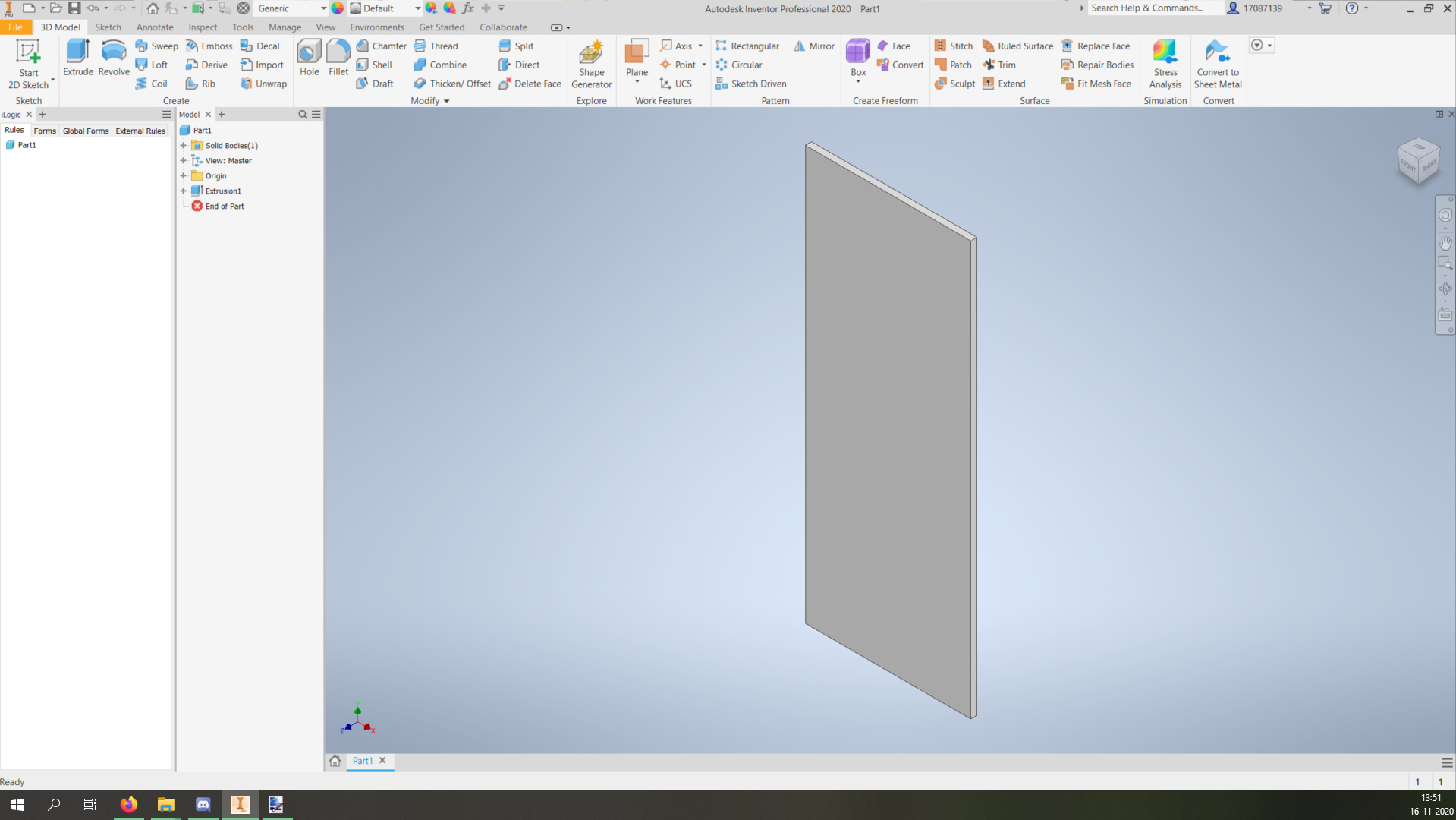
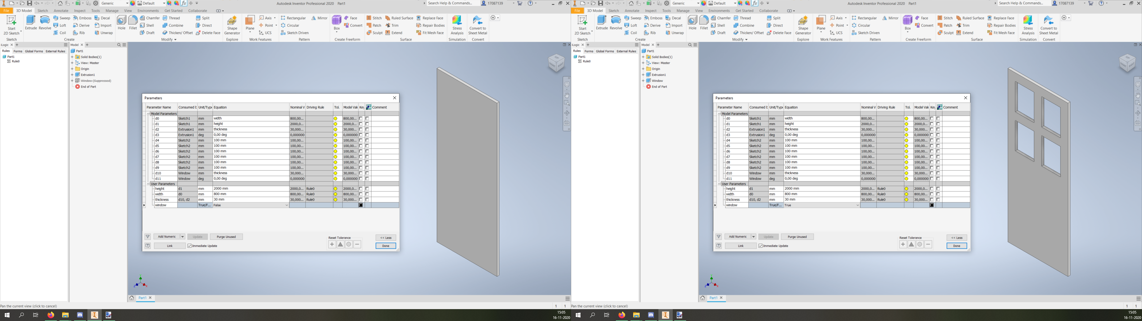
In this example we will be making a door for a house. For the door, we can make 3 user parameters before we start writing code. So go to the parameters and add height with a value of 2000, width with a value of 800 and thickness with a value of 30. Make a 2D sketch with a rectangle with the height and width and extrude it by the thickness. This should give the following “door”:
Once this is set up we can make our first rule. To do this, right-click under your part name in the iLogic browser and it will give the option to “Add Rule”, click this and give the rule a name. Now the following programming interface will open:
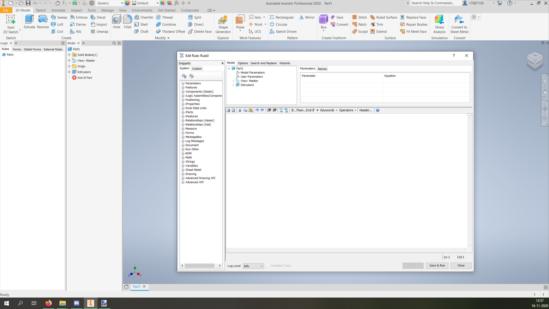
In this interface, there are a lot of options to program complex models but for now, we will write a function that limits the dimensions of the door. You can give this a go yourself or you can paste in the code below:
If height > 2300 Then
	height = 2300
Else If height < 1900 Then
	height = 1900
End If

If width > 1300 Then
	width = 1300
Else If width < 700 Then
	width = 700
End If

If thickness > 80 Then
	thickness = 80
Else If thickness < 20 Then
	thickness = 20
End If
After this code is made you can press save and close the interface. Whenever a parameter is changed this code will now automatically run (can be changed under options). Now give it a try! Change the parameters to weird values and see how they change back automatically to the specified range. This is just a simple example but you can imagine the options are endless with the ability to program whatever you want.
iLogic functions
This part will go on to show a few basic functions in iLogic which are very useful. To do this we will go on with the example of the door started in the parameters part of this module.
Messagebox
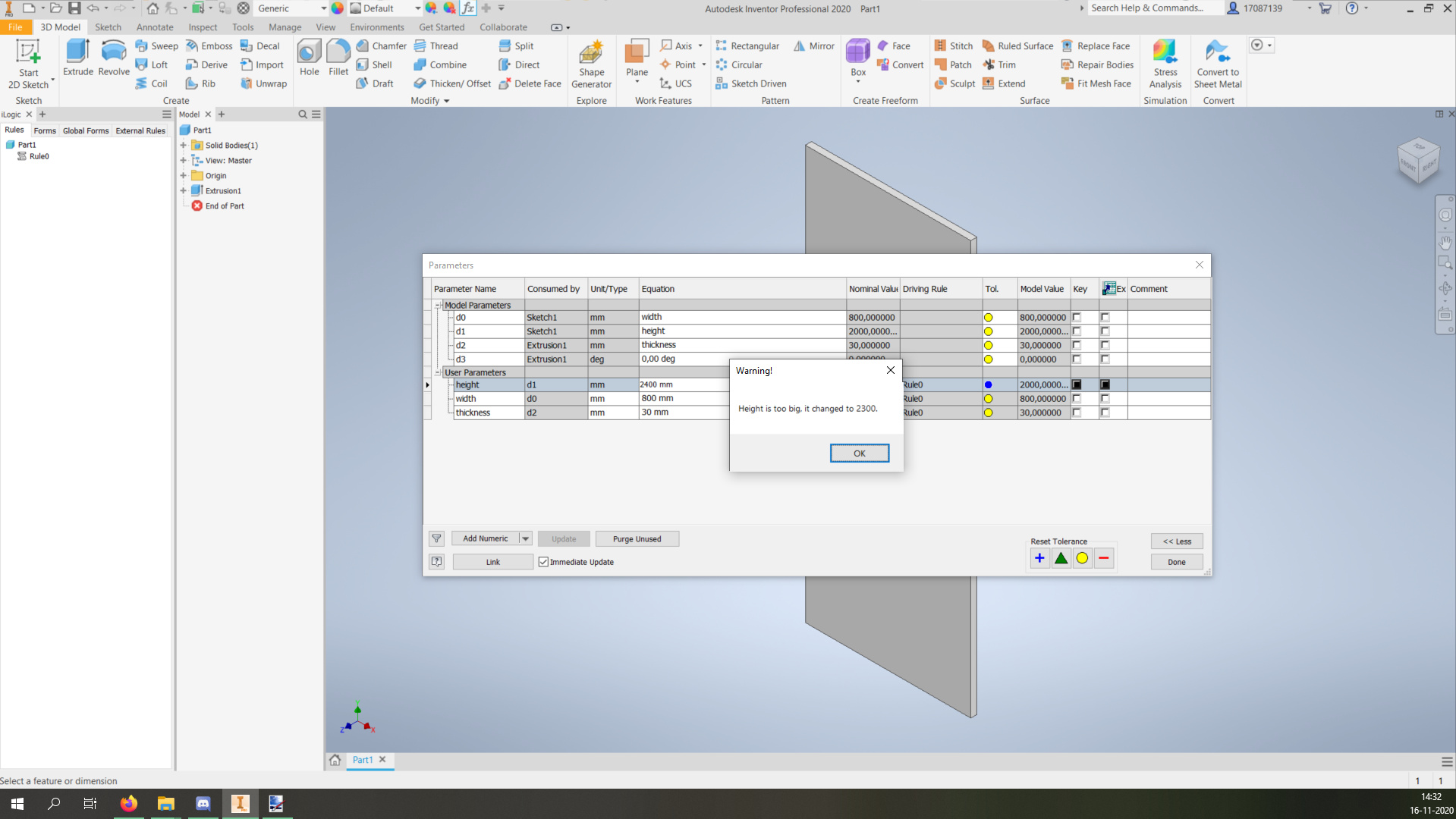
So, in the previous part we made it so that the dimensions of the door were limited to a set range. However, it did not give a warning or anything when this happened. To do this the MessageBox function is a handy tool. To add this MessageBox go back to your rule. How to use the code can be found on the left side under “Snippits”. Snippits are handy pieces of code already put together to directly implement in your code. To get a message box click the + in front of MessageBox to open up the folder with MessageBox types. For now we will use the simplest version called Show. Create a clear row on line 2 above “height = 2300” and put your cursor on that line. Now click “Show” under the Snippets tab. Replace “Title” with “Warning!” and replace “Message” with “Height is too big, it changed to 2300.”. Click Save and try to change the height to 2400. This should now result in the following:
The MessageBox is useful for giving users information, but it is also super handy to give yourself information when debugging your code. It is also possible to make a more complex MessageBox with for example YesNo buttons, a textbox, or even a file browser
Features
Features is another a handy tool to make parts which are easy to change, to demonstrate this function we will add a window to the door. To make this window make a sketch (challenge yourself by making the window variable sizes based on the door sizes) on the existing door and extrude this window into the door. After the extrusion is made it should be renamed to “Window”. Then add a user parameter with a boolean type (“Add True/False instead” of “Add Numeric”) and call it “Window” as well. Now go back to your rule.
On the bottom of your rule use the IsActive snippet under Features. Replace “featurename” by “Window” (the name of our extrusion) and add " = window" in the end (the name of our parameter). The line should now look like this:
Feature.IsActive("Window") = window
Save and close the rule again. When you now toggle the “window” parameter from true to false or false to true it should toggle the window from existing to non-existing and vice versa! This is of course super useful for complex models with many variants.
Inventor objects
In Inventor a lot of information is stored to be found back later in objects. Those objects can be found through a complicated mind-boggling infrastructure called the Inventor object model. (see link below)
InventorObjectModel.pdf (1.2 MB)
Instead of using this complicated diagram, it is usually easier to just mess around for a bit until you find what you need. Inventor iLogic has pretty good suggestions on what you might be looking for.
the Inventor Forums also have a lot of information on what to use to find certain things when you can not figure it out by yourself. This all might sound confusing and abstract, so let’s get going with a few code examples which can be copy-pasted into iLogic rules to do certain things for you. Messing around with this is by far the best way to understand how it works, so feel free!
Getting the name of the current file
The following code will give the filename in a string, and show it in a MessageBox (make sure to give it a name first by saving the file)
FileName = ThisDoc.FileName
MessageBox.Show("This file is named: " & FileName, "Demonstration")
In this code ThisDoc references to the document where the rule is run, and FileName references to a property of the document. This is similar to classes in Python for example.
3D sketch information
Getting a filename is relatively easy since it is quite an important piece of information for a document and therefore stored high up in the object model. Something more challenging is to get information from a 3D sketch for example. This requires you to dig deeper down to find what you need. To following code is an example of how you can get the XYZ from the start and endpoints of all lines in all 3D sketches in an Inventor part. First, the code will be given to try yourself, and after that, it will be broken down into pieces.
ThreeDsketches = ThisDoc.Document.ComponentDefinition.Sketches3D
For Each ThreeDsketch In ThreeDsketches
	Lines = ThreeDsketch.SketchLines3D
	For Each Line In Lines
		StartPoint = Line.StartSketchPoint
		EndPoint = Line.EndSketchPoint
		xStart = StartPoint.Geometry.X
		yStart = StartPoint.Geometry.Y
		zStart = StartPoint.Geometry.Z
		xEnd = EndPoint.Geometry.X
		yEnd = EndPoint.Geometry.Y
		zEnd = EndPoint.Geometry.Z
		popupText = (xStart & " " & yStart & " " & zStart & " " & xEnd & " " & yEnd & " " & zEnd)
		MessageBox.Show(popupText, "Demonstration")
	Next
Next
The first line starts with collecting all a list of all 3D sketches. (ThisDoc.Document.ComponentDefinition.Sketches3D returns an array with all 3D sketches with their information)
The next line opens each 3D sketch individually using a for loop (similar to “for item in array:” in python) Then each 3D sketch contains a lot of information on its own, The information we want is the lines in the sketch. This can be obtained using .SketchLines which is a function to extract an array of all lines in a sketch. In this code there is a second for loop to go through each line piece. Then again each line piece carries more information about itself. In this case, we are interested in the begin and endpoints which can be extracted using .StartSketchPoint and .EndSketchPoint. Those functions return points which also contain information on their selves. The information we want is the Geometry of the point which can be found with .Geometry and from the Geometry we want the XYZ coordinates which can be found with .X, .Y and .Z This sounds extremely complicated but when you start working with it it is not too bad. Just give the variables clear names and things will be easy to find and traceback. One thing to be careful with though is the fact that Inventor is kinda arbitrary when it comes to units, so sometimes your model might be set to mm as units, but the object model will trow cm as units to you, this is easy to solve by multiplying by 10, but it can lead to a lot of confusion so be careful!
It might seem useless at first to gather this information, but it can be really handy to export this data to a CSV for example to then use this information in a python script. A more in-depth explanation on using this information externally can be found in this article. It can also be useful to gather information about the material and mass of a part for example to make quick automated cost estimations in the designing phase.