This How-to guide walks through the process of modeling a camera mount for the Intel RealSense D435.
The camera itself has one larger threaded hole and two smaller ones. We initially attempted to use them but they were not sufficient to keep the camera securely in place.
The first step was to design a holder for a 40×40 aluminum profile, which also allows the camera’s position to be adjusted along the bar. A CAD file of the aluminum profile can be found online, and it can then be used as a reference to model a correctly sized holder. Here is an example of our holder.
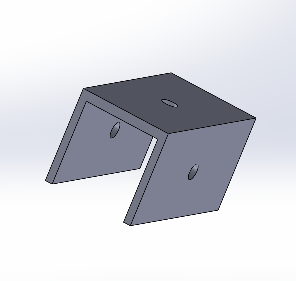
The camera mount can be attached to any side, depending on the requirements of the project.
Next, the camera needed a mount to which it could be attached. This can be designed in various ways depending on preference, but this particular design best suited our project and its requirements.
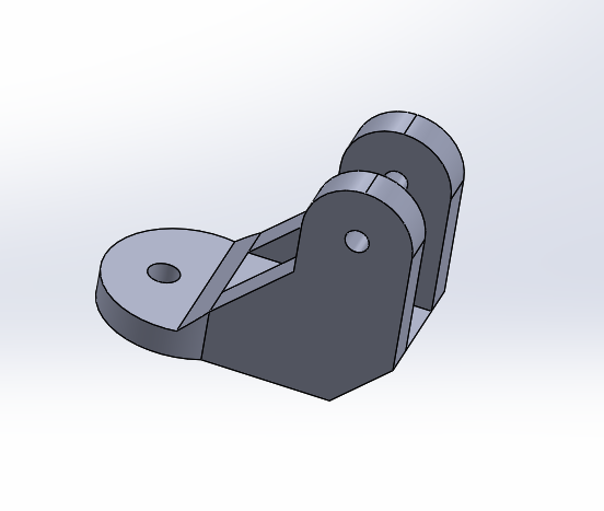
With this design solution, we were able to rotate the camera 360 degrees to achieve the desired position. The tightening is done with a nut that goes through both parts and is secured to the aluminum profile.
The final part is the actual camera holder. In this solution, the holder is attached with a nut to the other part of the mount, allowing us to adjust the angle at which the camera points downward.
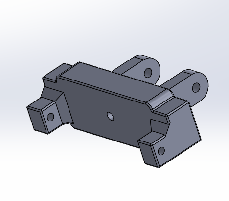
The holes on the side are for screws used to secure the camera in place and keep it stable during the robot’s movement. A small padding was placed between the screws and the camera to prevent damage, while still allowing the screws to be tightened enough to keep the camera firmly in position.
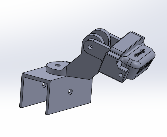
Here is an image of the full assembly.