I’m having a problem with figuring out how to control the IO pins on an upboard with python.
I use GPIO from the “periphery” library to try and set a pin to high. The library seems to work (although only if I run the python script as sudo) but nothing actually changes. I’m not getting any errors while running my script.
I enabled the IO pins in the BIOS.
Is there anyone with experience with the upboard who might be able to help me with this?
It is normal that you need to run the script as root (that is what sudo does), so keep that in.
Have you looked at the following:
- Are you using the right pin number? The numbers used in Python are different than the actual pin numbers. More information about the UP pin numbers and the ones in Linux can be found here: http://wiki.up-community.org/Pinout. You should use the Linux ones.
- How are you checking that the pin is on? If you use a LED: is it correctly installed (plus/minus and resistor) and does it work if you just connect the power supply? Further, are you connected to the right pins and is the other pin a ground pin?
- I’m pretty sure I’m calling the right pins. I’ve tried both the pin numbers from the upboard and upboard2 from the wiki. Guus looked at it with me and he thought I was doing it correctly.
- I’m using both a multimeter and a relay that I can hear click whenever it switches. I know the relay works because I checked with an “always on” 5V pin. Currently, nothing is connected to the other end of the relay yet, but the click is pretty obvious. I check all available pins with the multimeter whenever I (try to) switch something on to make sure I didn’t set the wrong pin.
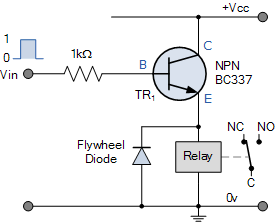
How did you connect the relay? Is it connected directly to the UP board or via a transistor?
If you haven’t used a transistor then there is a chance the GPIO you used is damaged and no longer works. Test another pin, but only with a LED (and resistor!) or a multimeter.
If you’re using a transistor, how is it connected and does the relay turn on if you connect the base of the transistor (also via a resistor) to 3.3v?
Or are you using an off the shelf relay board with build in transistor?
Some background:
The problem with these board is that the GPIO pins can’t handle much current. For the UP board this is max. 24 mA (see: Pinout · up-board/up-community Wiki · GitHub). This is far to little to run a relay. Therefore some sort of buffer is needed, for example a transistor.
I found the problem: I had a software issue after all. Apparently you need a specific kernel to access the GPIO pins, as explained over here: http://wiki.up-community.org/Ubuntu#Install_Ubuntu_kernel_for_UP_from_PPA (useful for other students in the future).
I can now control the relay with the upboard.
I currently have the relay signal in hooked up straight to the IO-pin of the upboard and the relay signal out to the gnd on the upboard; I don’t use a transistor to connect the relay. From your explanation it sounds like I really should. I don’t know much about electronics, but to me this looks like using a “mini-relay” to switch the relay. is that what it does?
Glad you figured it out.
So the latest specific kernel you need in order to use the pinout is to this date:
Linux 4.10.0-42-generic #5000~upboard9-Ubuntu
Are you still using the periphery library?
Yes, a little bit. A relay is a mechanical switch, a transistor purely an electrical switch.A transistor is mostly used for switching small electric load, for example: turning on and of a relay.
I am indeed still using the periphery library
