Based on contributions by Kevin.
An air-cushion track lifts an object on a thin layer of air, giving a nearly frictionless surface to slide it across — the same principle used in an air-hockey table. This covers the two main design choices and the physics behind sizing the air holes and flow.
What you need
- A blower or fan capable of sustained airflow (not necessarily high pressure)
- A surface you can drill small holes into (e.g. a 3D-printed or machined plate)
- If supplying air from one point: a splitter to distribute it evenly
Background
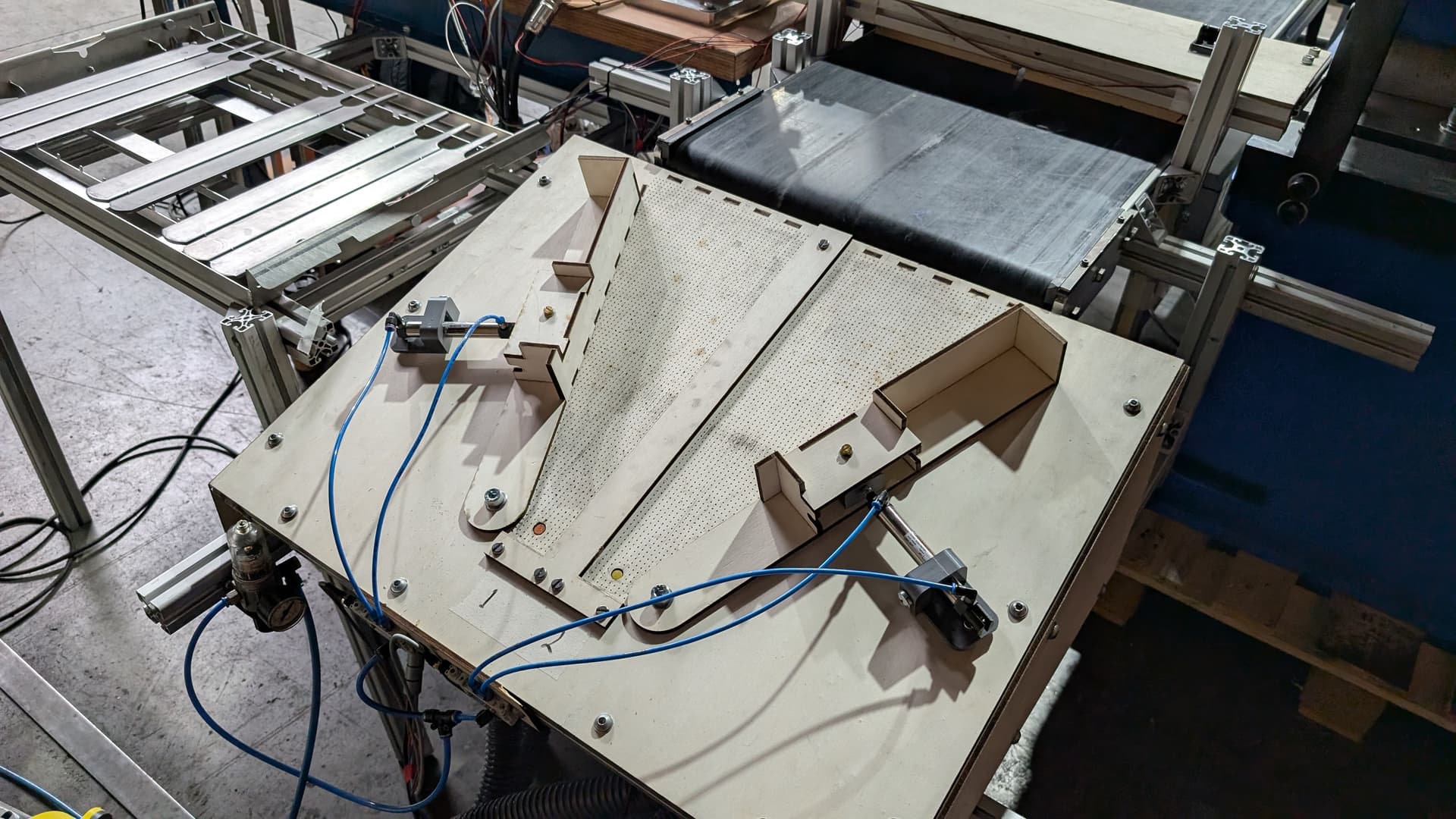
Air-cushion tracks can be built in one of two ways: an air-rail blowing along either side of the object, or a direct air-pushing surface underneath it (this guide covers the latter). A common industrial use is catching vials as they exit a conveyor belt: the vials have ridges that would normally stop them sliding, but the air cushion removes most of the friction, letting them slide smoothly into a funnel.
Steps
1. Choose your air supply
Airflow matters more than air pressure — the cushion doesn’t need much pressure to create lift, but it does need enough flow rate to lift the object. A blower is a good choice; a large fan underneath the surface would likely also work.
2. Choose hole size and spacing
The exit airflow is controlled mainly by hole diameter and hole spacing (which together determine how many holes fit on the surface). Holes can be quite small — one build used 0.75 mm holes spaced 5 mm apart.
3. Design the air supply distribution
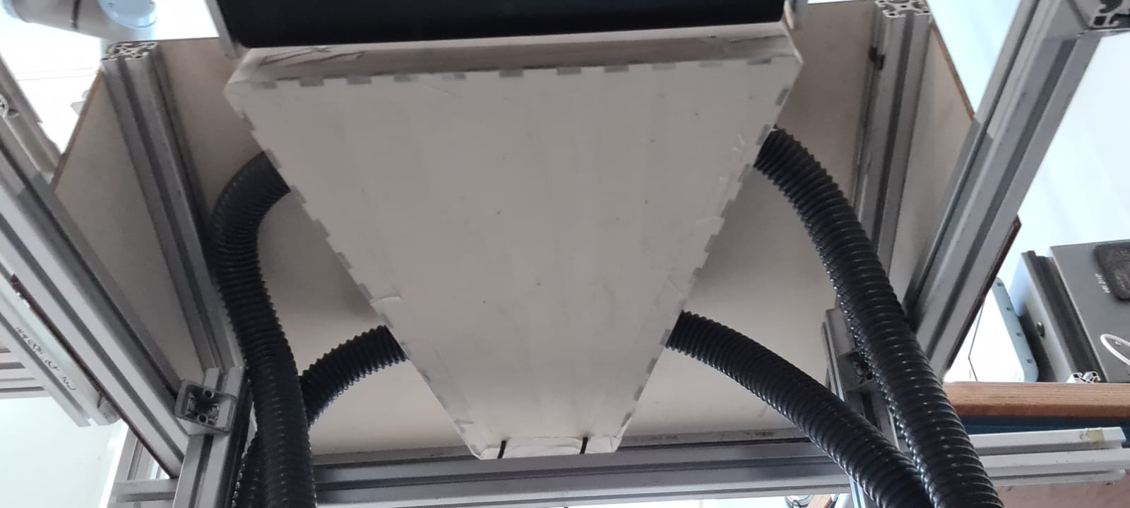
Make sure air is distributed evenly into the pocket under the holes. If you feed air in from only one side, that side gets more flow than the far side, causing uneven lift across the surface ( Check: the original description of this effect was unclear — this is our best interpretation). One build 3D-printed a splitter mounted on the blower outlet, feeding four tubes into the four corners of the air pocket for even distribution.
Calculating flow and hole sizing
For small SMR projects, it’s usually faster to experiment (following the guidelines above) than to fully calculate the required airflow, hole size, hole spacing and pressure. If you do need to implement this professionally, the formulas below relate the key values:
Q— air flow rateA— total surface area of all holesD— diameter of each holed— distance between holesP— required pressure under the object
Required pressure to lift the object:
P = (m × g) / A
m= mass of the object (kg)g= gravitational acceleration, 9.81 m/s²A= area of the bottom of the object (m²)
Required flow rate through the holes:
Q = C × A × √(2P / ρ)
C= discharge coefficient of the holes (a standard orifice-flow constant, typically ~0.6–0.8; not measured in the original build)ρ= density of air (≈ 1.2 kg/m³ at room temperature)
Choose the hole diameter and spacing so that the total hole area across the surface matches the flow and pressure the object needs.
Related
- Choosing between pneumatic and electric actuators — pneumatic vs. electric actuation, if you’re deciding between an air-based solution and a motor-based one
Rewritten and consolidated (Sept 2026) from the original student how-to’s: How-to design an air-cushion track.