Based on contributions by Okay.
Making parts on a mill, CNC, or by hand usually requires a dimensioned 2D drawing, not just the 3D model. This walks through creating a 2D drawing from a SolidWorks part or assembly.
What you need
- SolidWorks.
- A finished part (
.SLDPRT) or assembly (.SLDASM).
Steps
1. Open your 3D model
Launch SolidWorks and open the part or assembly file you want to create a drawing from.

2. Start a new drawing from the part
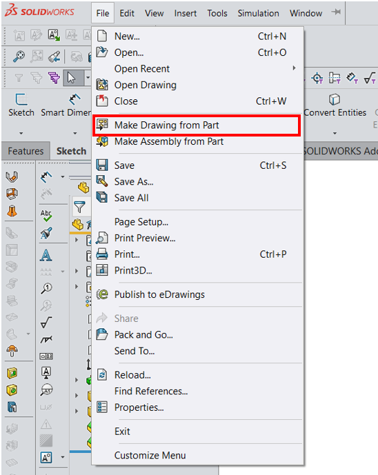
Go to File → Make Drawing from Part.
3. Insert standard views
-
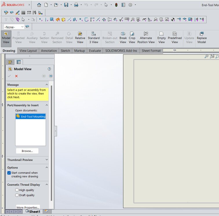
In the Model View window that appears, select your 3D model file.
-
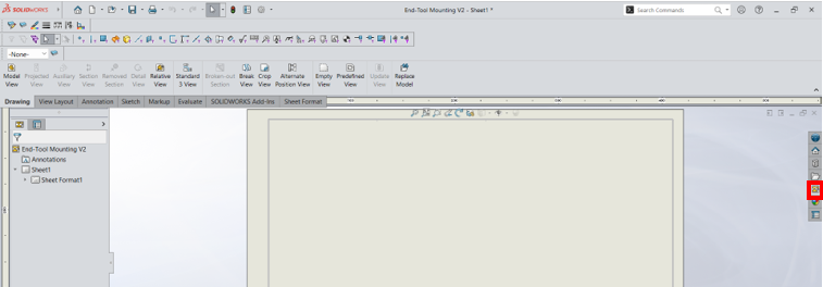
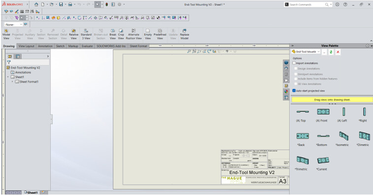
Drag and drop the views you need (front, top, side, etc.) onto the drawing sheet. Choose them from the View Palette on the right side of the screen.
-
Add additional views with Projected View, dragging out projections such as isometric or auxiliary views.
4. Add dimensions
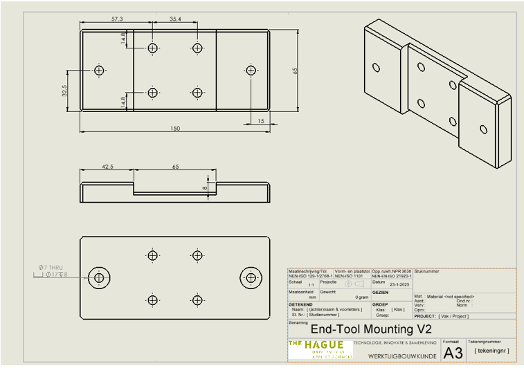
Go to the Annotations tab and click Smart Dimension. Click on edges, holes, or other features of the model to place dimensions automatically.
5. Add other annotations (optional)
Add centerlines, center marks, or notes from the Annotations toolbar as needed for someone else to manufacture the part correctly.
6. Save the drawing
Save the drawing as a SolidWorks Drawing file (.SLDDRW), or export it to another format such as PDF via File → Save As and selecting .PDF.
Related
Rewritten and consolidated (Sept 2026) from the original student how-to’s: How to make a 2D drawing from 3D model in Solidworks.