Based on contributions by Luke.
Some sensors output a signal too weak for the Doosan controller’s digital input to detect reliably. Routing the sensor through a microcontroller first — which reads the signal, cleans it up, and forwards it over serial — is a workaround that lets you process the signal in Python before acting on it.
What you need
- A sensor with a digital output (e.g. a photoelectric sensor)
- An Arduino (or similar microcontroller)
- A breadboard and jumper wires
- A PC running Python with the
pyserialpackage (pip install pyserial) - The sensor’s datasheet, to confirm its required voltage and wiring
Steps
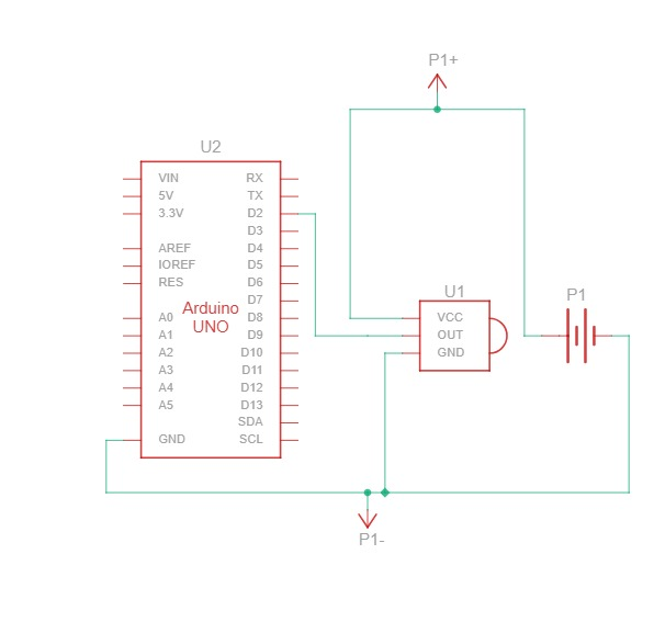
1. Wire the sensor to the Arduino
- Connect the sensor’s signal output to a digital input pin on the Arduino.
- Use a breadboard to connect the sensor’s V+ and GND.
- Check the sensor’s datasheet for the correct supply voltage and wiring before powering it up.
2. Read the digital input on the Arduino
if (digitalRead(SENSOR_PIN) == LOW) {
    count++;
    Serial.print("Count: ");
    Serial.println(count);
}
This checks whether the sensor has triggered, and prints a running count over serial.
3. Connect to the Arduino from Python
import serial

arduino = serial.Serial('COM11', 115200, timeout=1)  # edit the COM port and baud rate to match your setup
4. Read the serial data in Python
if arduino.in_waiting > 0:
    count_value = arduino.readline().decode().strip()
    print("Count from Arduino:", count_value)
This reads a line from the Arduino’s serial output and prints it.
Check: this only prints the count to the terminal. It does not forward the value into the Doosan’s own program — if you need the robot to act on it, you still need to add that link yourself (for example, opening a TCP connection from the robot’s DRL program to the PC, or driving one of the robot’s digital/analog inputs from the microcontroller — see How to connect a Doosan digital I/O port to a microcontroller using a transistor and How to use the analog I/O ports on a Doosan robot).
5. Test in the real environment and eliminate false positives
Sensors can behave differently once installed, depending on lighting, vibration, motion, or electrical noise — test in the actual working environment, not just on the bench:
- Run the sensor with the Arduino connected and watch the serial output.
- Trigger the sensor intentionally (e.g. place an object in front of it) and confirm the Arduino registers it consistently.
- Watch for false triggers — random count increases with no real trigger.
Troubleshooting
Reduce false positives with debounce logic, especially for mechanical switches or IR sensors:
if (digitalRead(SENSOR_PIN) == LOW && millis() - lastTriggerTime > 200) {
    count++;
    lastTriggerTime = millis();
    Serial.println(count);
}
Or require a stable reading over several samples before counting it as a real trigger:
bool stableLow = true;
for (int i = 0; i < 5; i++) {
    if (digitalRead(SENSOR_PIN) != LOW) {
        stableLow = false;
        break;
    }
    delay(2);  // 2ms between checks, 10ms total
}

if (stableLow) {
    count++;
    Serial.print("Count: ");
    Serial.println(count);
}
If false positives persist:
- Add a small delay between readings to reduce noise/bounce.
- For analog sensors, add a capacitor or a software filter to smooth unstable signals.
- Physically isolate the sensor from vibration or electrical noise sources.
- Use shielded or twisted-pair cable for longer runs, especially near motors or high-voltage lines.
- Double-check the sensor’s voltage/current specs against what the Arduino and the sensor’s own power source actually provide.
Related
- How to connect a Doosan digital I/O port to a microcontroller using a transistor
- How to use the analog I/O ports on a Doosan robot
Rewritten and consolidated (Sept 2026) from the original student how-to’s: How to connect sensors to a Doosan PLC (when output signal is weak).