Based on contributions by Jeppe.
This tutorial builds a fully parametric coffee cup to get comfortable with parametric modelling: driving a shape from named parameters instead of fixed dimensions. It works in Inventor, SolidWorks, or Fusion 360 — the tools have different names but the same workflow.
What you need
- Any parametric CAD package (Inventor, SolidWorks, or Fusion 360).
- No prior parametric modelling experience required.
Steps
1. Set your design requirements
Before modelling, decide what should stay adjustable. For this cup:
- Height
- Diameter
- Wall thickness
- Wall angle
2. Create a new part
Create a new part file and save it (e.g. coffee_cup). This is the file you’ll work in for the rest of the tutorial.
3. Open the parameters/equations tool
Where you manage parameters depends on your software:
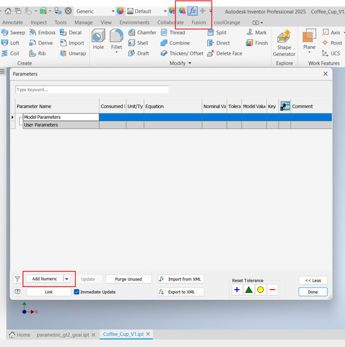
- Inventor: the Parameters tab is at the top of the program. Click Add numeric to add a numeric parameter.
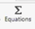
- SolidWorks: search “Equations” in the command search bar. You can drag it into your toolbar for faster access later.
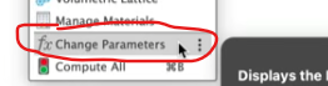
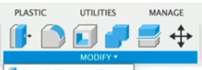
- Fusion 360: open the Modify dropdown menu → Change Parameters.
4. Add the parameters
Add parameters for height, diameter, wall thickness, and wall angle, using these starting values:
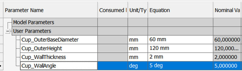
Set the correct units on each parameter so the software interprets your values correctly.
5. Sketch a revolve profile
Create a new sketch. Put it on a plane that passes through the center of the cup (e.g. the XY plane). Instead of sketching the full cup cross-section, sketch only half of the cup profile next to a centerline — you’ll revolve it 360° around that centerline to get the full cup. This is faster and keeps the sketch symmetric by construction.
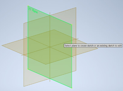
Follow along with the recorded walkthrough of the sketch:
6. Drive the sketch dimensions with your parameters
Link each sketch dimension to the matching parameter (height, diameter, wall thickness, wall angle) instead of typing a fixed number.
Two common mistakes to avoid (both happen in the video, and are corrected there):
- Diameter dimensioned as a radius. If you dimension a line by itself instead of dimensioning it in relation to the centerline, you’ll actually get the radius, not the diameter. Always dimension from the centerline when you want the diameter parameter to control the full width.
- Wall angle offset. The
WallAngleparameter should be set to 90° + whatever draft angle you actually want, not the draft angle by itself.
7. Revolve the sketch
Revolve the profile 360° around the centerline. You now have a fully parametric cup — change any parameter and the model updates.
Troubleshooting
- Cup diameter doesn’t match the parameter you set — check that the diameter dimension is measured relative to the centerline, not just on the profile line (see step 6).
- Wall angle looks wrong — remember
WallAngleis 90° plus your desired draft angle, not the draft angle on its own. - A tool from the tutorial isn’t in your software — search for the closest equivalent to the Inventor tool name; most parametric CAD packages have a matching feature under a different name.
Related
Rewritten and consolidated (Sept 2026) from the original student how-to’s: Beginners parametric CAD Design tutorial.