Based on contributions by Merv.mg.
This is a step-by-step guide to running a basic static stress analysis on a SolidWorks part, for when you need to check whether a design will hold up under load but haven’t used SolidWorks Simulation before.
What you need
- SolidWorks with the Simulation add-in.
- A finished 3D part.
- The material and expected load(s) for the part.
Steps
1. Enable the Simulation add-in
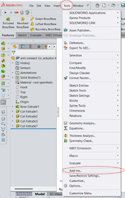
- Go to Tools → Add-Ins.
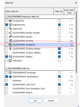
- Check the box next to SolidWorks Simulation.
- This adds the Simulation tab to the SolidWorks interface.
2. Set up a new simulation study
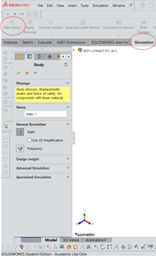
- In the Simulation tab, click New Study.
- Select the analysis type — for stress analysis, choose Static.
- Name the study and click OK. This creates a new Simulation study tab.
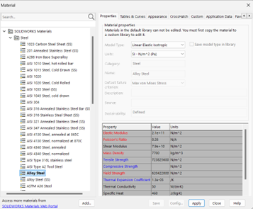
3. Apply material
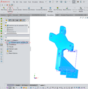
- Select the part.
- In the Simulation tab, click Apply Material.
- Select the material the part will actually be made of.
4. Apply fixtures
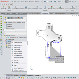
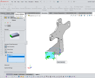
- Right-click Fixtures in the Simulation tree and choose the appropriate fixture type (e.g. Fixed Geometry, Roller/Slider).
- Click the faces where the constraint applies. Fixtures prevent movement and rotation in the specified directions.
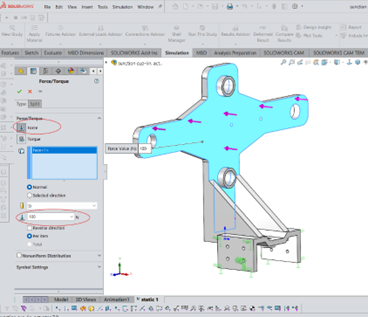
5. Apply external loads
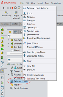
- Right-click External Loads in the Simulation tree and select the load type.
- Select the surfaces or edges where the load applies.
- Specify the magnitude and direction of the load.
6. Mesh the model
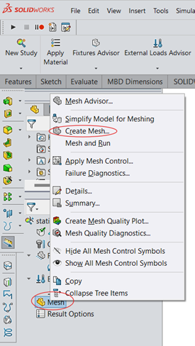
- Right-click Mesh in the Simulation tree and select Create Mesh.
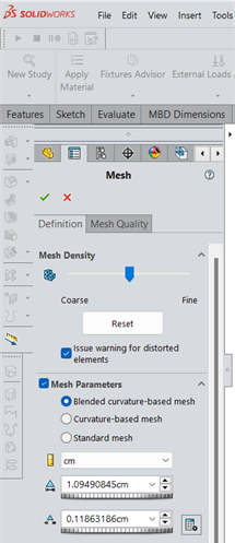
- Adjust the mesh density as needed — a finer mesh is usually more accurate but takes longer to compute.
- Click OK to generate the mesh.
7. Run the analysis
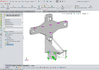
Once fixtures, loads, and mesh are set, click Run in the toolbar to start the simulation.
8. Review the results
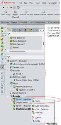
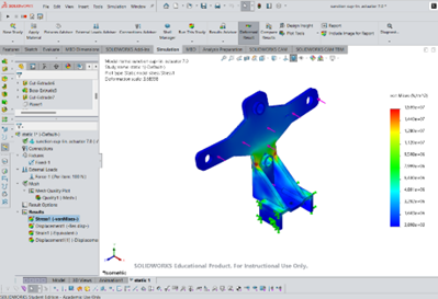
Right-click Stress and select Show Plot to view the stress results.
Troubleshooting
- Deformation is very large or the study doesn’t converge — a static study assumes small, linear-elastic deformation. If your load causes large or plastic deformation, use a nonlinear study instead — see How to use SolidWorks Design Study to estimate forces on an oddly shaped part.
- Simulation tab is missing — recheck the add-in is enabled under Tools → Add-Ins.
Related
Rewritten and consolidated (Sept 2026) from the original student how-to’s: How to perform a stress analysis on a CAD model using SolidWorks.