Based on contributions by alexandra.
Most Design Study tutorials use simple, regular 3D models. This guide instead covers estimating bending forces on an irregular, real-world part — the kind of oddly shaped component you actually run into in a machine design project — using SolidWorks Simulation’s Design Study.
Use this when you need to estimate the force involved in deforming or prying open a part, especially when you’re automating something that used to be done by hand: getting the force estimate right matters for both mechanism sizing and operator/robot safety.
What you need
- SolidWorks Education with the Simulation add-in enabled.
- A 3D model of the component.
- Basic knowledge of setting materials, fixtures, and loads in SolidWorks Simulation.
Steps
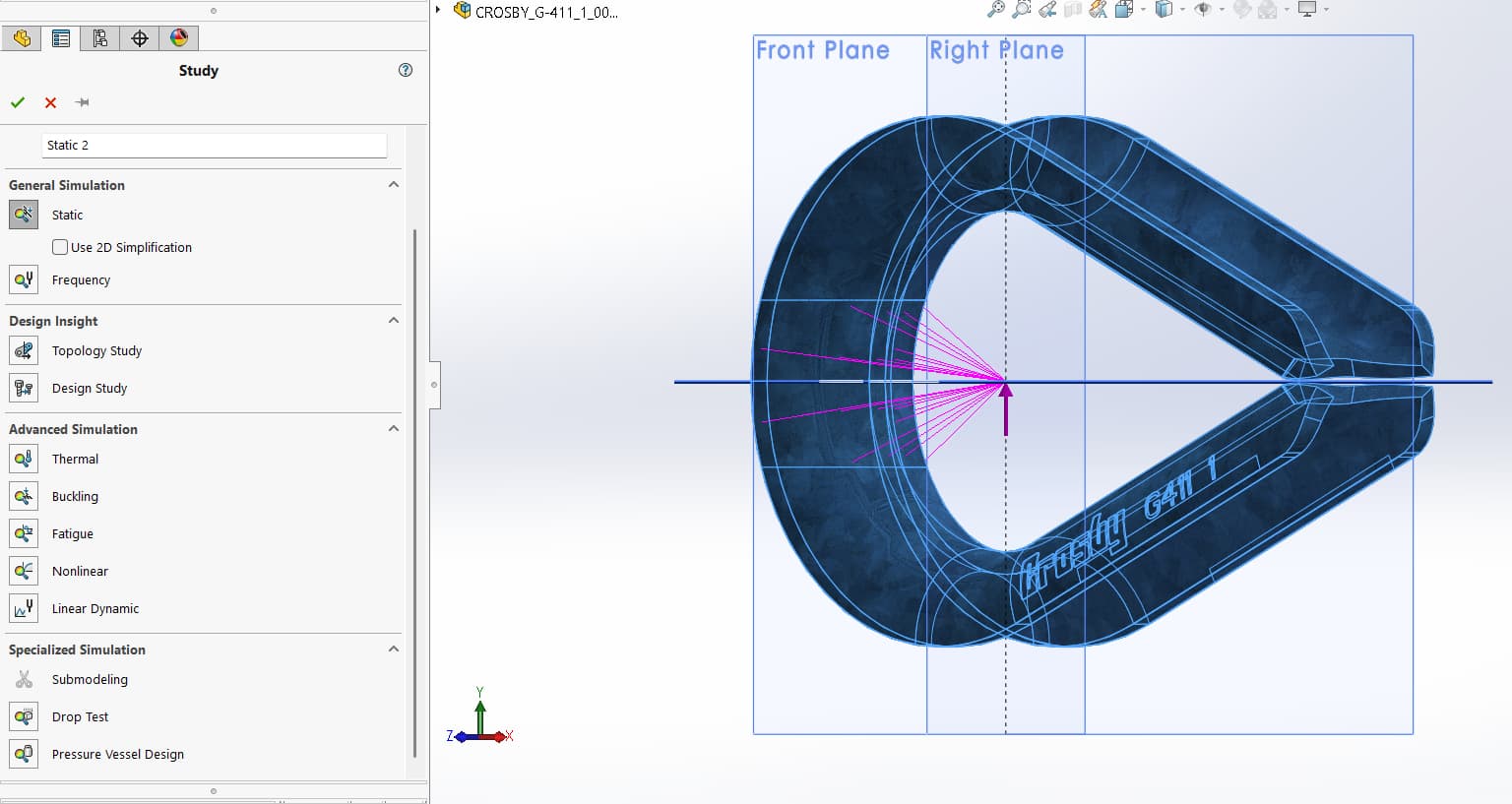
1. Choose the right study type
Go to Simulation → Study → New Study, and choose Static or Nonlinear depending on the material’s expected behavior. Use Nonlinear if the part will undergo large deformation or plastic bending (as with prying open sheet metal or a bent hook/thimble) — a static study assumes small, linear-elastic deformation and will give misleading results for that kind of loading.
2. Set the material
Choose the material for the 3D model. This depends on the actual part and the study you’re trying to run — for example, a galvanized steel thimble used in marine logistics that needs to be pried open.
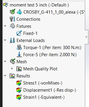
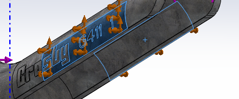
3. Set up fixtures
Set fixtures based on how the object is actually held in place. For example, a thimble held in a mechanical vice:
4. Apply the loads
Apply loads based on what you actually know:
- Displacement, if you know the distance you want the part to move or deform to.
- Force, if you’ve measured the force accurately.
- Torque, if the object is being twisted.
Other external loads can be added depending on what your design study needs to capture.
5. Mesh and run the study
Mesh the model, then run the study.
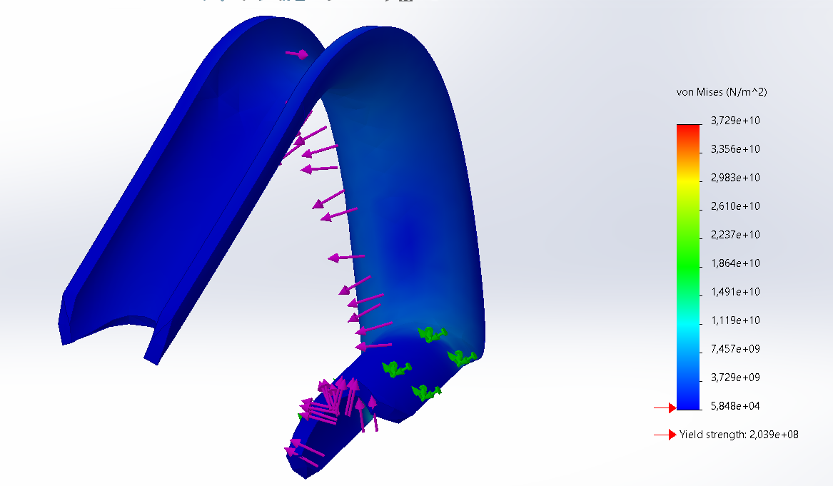
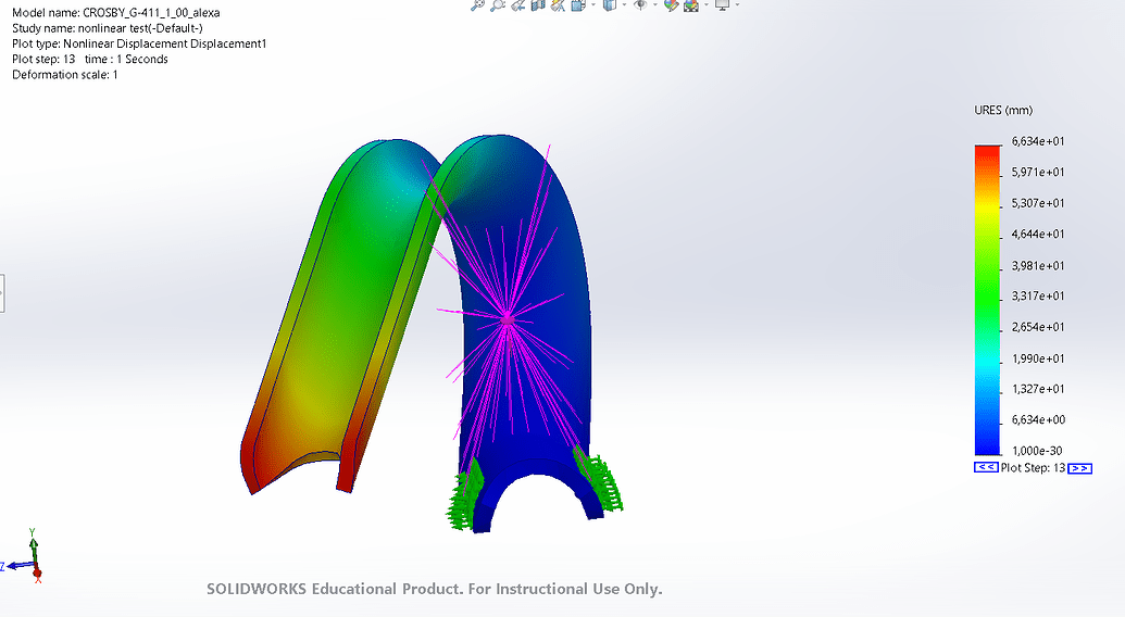
6. Read the results
Review the resulting stress/force values against your requirements. If the study is meant to size an actuator or motor for an automated system, use the reaction force at the fixture (or the load needed to reach your target displacement) as your design number, and add a safety margin before selecting hardware.
Troubleshooting
- Results look unrealistic for a bending/prying scenario — check you used a Nonlinear study, not Static; large deformation needs the nonlinear solver.
- Study won’t run / Simulation tab missing — confirm the Simulation add-in is enabled and that you have a SolidWorks Education license with Simulation included.
Related
Rewritten and consolidated (Sept 2026) from the original student how-to’s: How to use design study in SolidWorks for determining forces.