Based on contributions by Erik_Endlich.
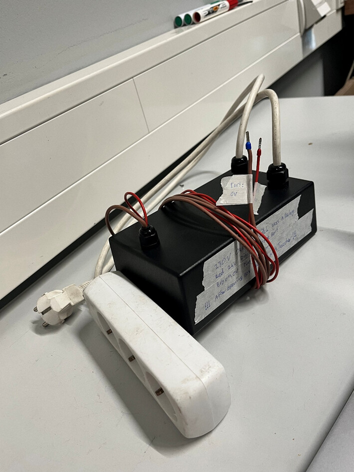
The lab has a pre-built 230V power-outlet switch: an extension cord whose power is switched on and off by a safety relay, controlled from a robot controller’s digital output. Use it whenever a project needs to switch mains power under program control. It’s already cleared by a teacher for plug-and-play use as-is.
Always check with a workshop teacher before plugging anything into mains power. See also the general safety guides: This is what your electrical box should look like and Electronics 101 Download.
If you change anything about the wiring inside the box, a teacher must re-check it for safety before use.
What you need
- The lab’s 230V power-outlet switch unit (extension cord + PNOZ X7 relay, pre-built)
- A robot controller with a 24V digital output and a 0V port
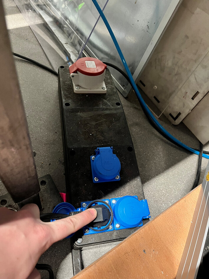
- One of the lab’s black power outlets (see safety note below)
Steps
1. Connect the control signal
Plug the red wire into a 24V digital output port on your robot controller, and the brown wire into a 0V port.
2. Plug into a lab power outlet only
3. Switch it
Once the robot controller is connected and the extension cord is plugged into a black lab outlet, you can turn the power on and off either manually (via the digital output in the robot controller’s menu) or by programmatically toggling that digital output.
4. Unplug it at the end of the day
Always disconnect the extension cord from the power socket when you’re done for the day.
How the relay is wired (for reference / troubleshooting)
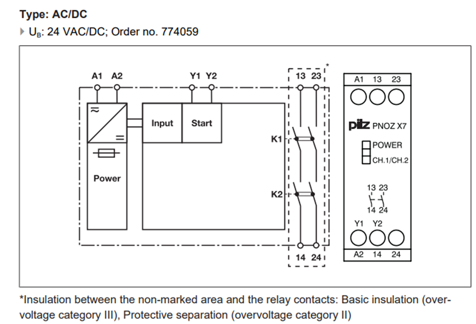
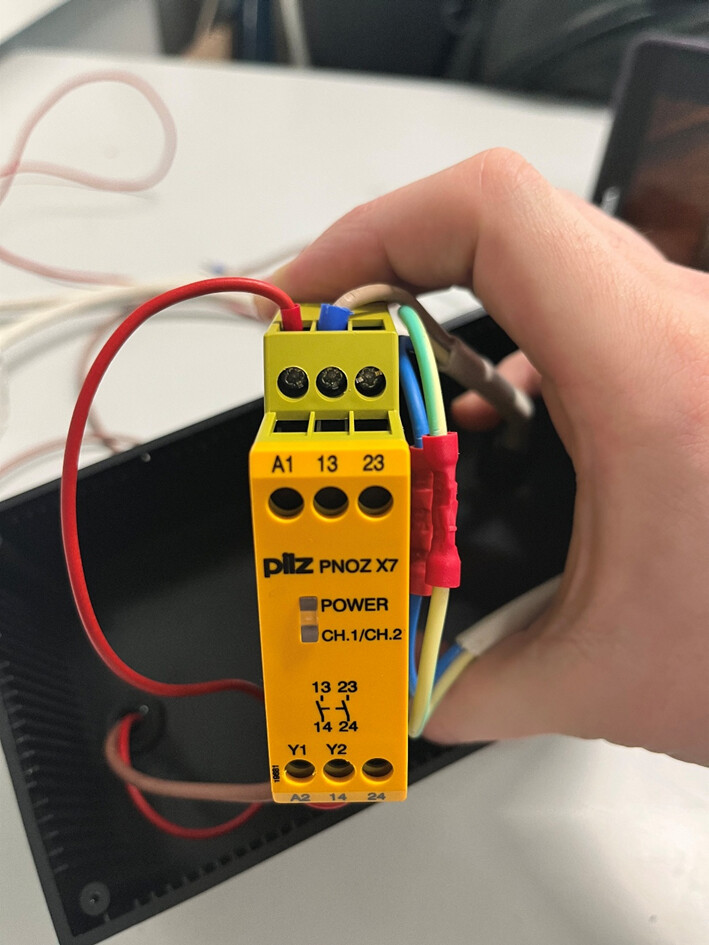
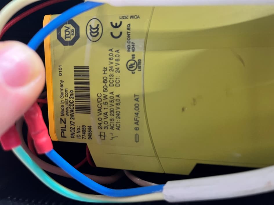
The unit is built around a PNOZ X7 safety relay:
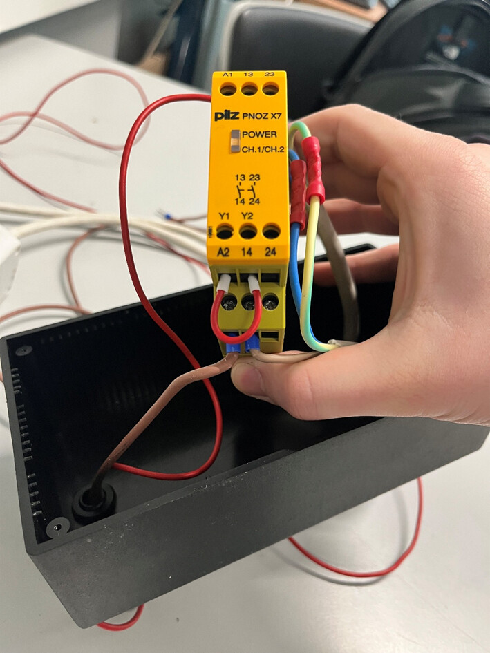
- The 24V control signal (red) goes to relay port A1, and 0V (brown) to port A2 — this is the coil that gets switched by the robot controller.
- The mains cable’s live (brown) wire is cut and connected through relay ports 13 and 14 — this is the switched circuit.
- Neutral and ground are passed through uncut, reconnected inside the box (they only needed to be opened to fit through the cable gland).
- Ports Y1 and Y2 are bridged with a short wire.
Related
- How to build an electric safety box for components above 25V — building an electric safety box
- How to switch higher-voltage loads with an Arduino (relay, optocoupler, H-bridge) — switching higher-voltage loads with an Arduino
Rewritten and consolidated (Sept 2026) from the original student how-to’s: How to use the 230V power-outlet switch.