Based on contributions by ThomasVrakking.
This describes the electrical wiring inside a typical conveyor belt control box: mains power in, safety switching, the frequency inverter (VFD) that drives the motor, and the E-stop / run / direction control wiring. Use it as a reference when building or troubleshooting a conveyor’s electrical box.
This is a mains-voltage (230 V AC) wiring job. Have the wiring checked by a qualified electrician before switching anything on, and always work with the main switch off.
What you need
- Conveyor with a three-phase motor and a frequency inverter (this guide was written for a Mitsubishi FR-D720S-025SC-EC; the terminal names are similar on most Mitsubishi FR-D700 series drives)
- Main switch
- Circuit breaker
- Distribution block(s) for phase/neutral and for earth
- Potentiometer (for manual speed control)
- Emergency stop switch
- Run/stop and direction switches
- The inverter’s manual, for your exact terminal layout and parameter settings
Steps
1. Power supply connection
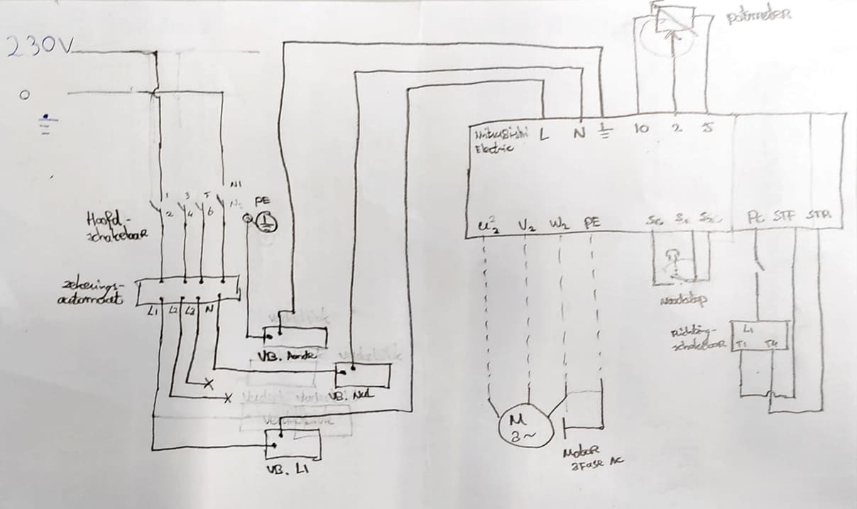
- Connect the 230 V AC supply (from a wall socket) to a main switch.
- The main switch splits the incoming power into:
- Phase (L)
- Neutral (N)
- Earth (PE – green/yellow)
2. Safety and distribution
- Connect the output of the main switch to a circuit breaker.
- From the circuit breaker, wire to a distribution block.
- From the distribution block:
- Phase (L) and Neutral (N) go to the input terminals of the frequency inverter (VFD).
- The earth wire (green/yellow) goes to a separate earth distribution block, then to the earth terminal of the VFD.
3. Connecting the frequency inverter (FR-D720S-025SC-EC)
- Connect the three-phase motor directly to the inverter’s output terminals U, V, W, and connect the motor’s earth to the VFD’s PE terminal.
4. Control wiring
-
Potentiometer connection (for manual speed control):
- Terminal 2: wiper (variable output from the potentiometer)
- Terminal 5: ground (GND)
- Terminal 10: potentiometer supply ( Check: the exact voltage/function of terminal 10 was not recorded in the original build notes — confirm against the FR-D700 wiring diagram before connecting)
-
Emergency stop switch:
- Connect the normally-open (NO) contacts of the E-stop to terminals S1 and S2.
- Terminal SC is the common return.
-
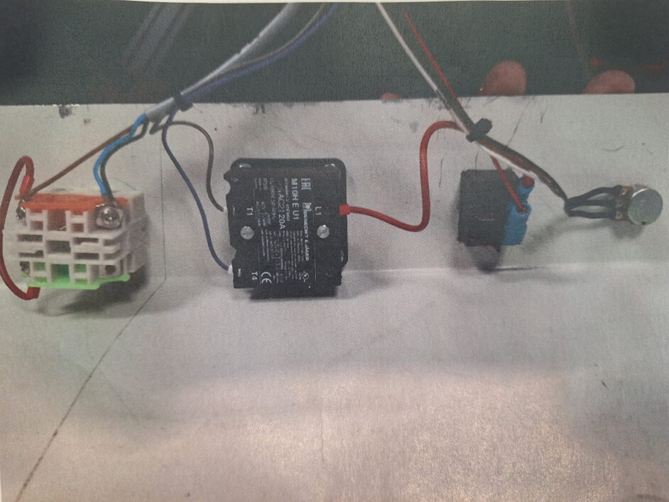
Run/stop and direction control (via switches):
- Terminal PC: common (connected to one side of both switches)
- Terminal STF: forward run command
- Terminal STR: reverse run command
Important notes
- The electrical box may contain extra components (a relay, an electrical socket, a 230→24 V power converter, a Mitsubishi servo amplifier) that are not needed to make the conveyor run — you’re free to use them for your own project, but you can ignore them for basic conveyor operation.
- Use safety rings and screws to attach the motor cap correctly.
- Always verify that the control terminals are configured correctly in the VFD’s parameters (e.g. set the input mode so STF/STR are used for run/direction).
- Follow the manufacturer’s official manual for the exact parameter settings and safety precautions for your inverter model.
- Have all wiring work done or checked by a qualified electrician, and make sure it complies with local electrical codes.
Related
- How to control a conveyor belt over Modbus-RTU from Python (Mitsubishi FR-D720S inverter) — control this same inverter over Modbus-RTU from Python instead of switches
- How to calculate motor power, RPM and torque for a conveyor belt — how to size the motor driving this conveyor
Rewritten and consolidated (Sept 2026) from the original student how-to’s: Using conveyor with big electrical box.