Based on contributions by Daan1, 20129556.
The T-verter E2 family of frequency inverters is used on several conveyor belts in the lab to drive the motor and control speed/direction. This guide covers the basic wiring and two different ways students have controlled it: directly from a robot’s digital I/O, and from an Arduino through a relay. Check which sub-model you have (the label on the drive) and use the matching section below — parameter numbers differ between sub-models.
Warning: the inverter uses mains voltage. Do not power it on before it is in a proper electrical box and checked by an electrical professional. Before powering it on, make sure you know whether your motor is star- or delta-connected — connecting it wrong can damage the motor.
What you need
- Conveyor belt with a T-verter E2 (220 V) or T-verter E2-201-H1F inverter
- 230 V AC supply
- For robot control: a robot/controller that can supply 24 V
- For Arduino control: an Arduino, a JQC3F-03VDC-C relay
- T-verter E2 manual (37388_E2Manual_Engels-V09.pdf)
Steps
1. Wire the motor and mains power
- Connect L1 and L2 to 230 V AC.
- Connect T1, T2 and T3 to the corresponding wires from the motor — this is a straightforward one-to-one connection.
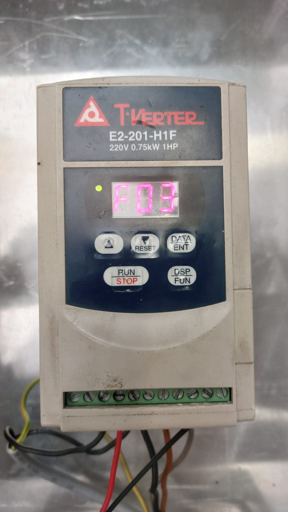
- With default settings, the belt can now be started/stopped with the start/stop button on the drive. The blinking value on the screen is the belt’s current speed.
2. Basic function reference
To navigate the drive’s menu: press the pyramid (▲) symbol to move up through functions, and the nabla (▽) symbol to move down. To edit a function’s value, press DATA/ENT, use ▲/▽ to change it, then press DATA/ENT again to confirm.
Common functions ( Check: function numbers vary between the plain “T-verter E2 220V” and the “T-verter E2-201-H1F” — confirm against your unit’s manual):
| Function | Purpose |
|---|---|
| F01 | Speed of the conveyor |
| F03 | Direction/input source select |
| F04 | Direction of the conveyor |
| F09 | Preferred/target speed |
| F10 | Enable external (e.g. Arduino) control |
| F19 / F20 | Enable input control mode |
3a. Option A — control from a robot’s digital I/O (T-verter E2, 220 V)
Used to run the belt from a robot (tested with a UR5), which supplies a 24 V digital output.
- Set F19 or F20 to
1. - Set F09 to your preferred speed.
- Set F03 to
0— this lets you control direction via the input terminals: input 3 = forward, input 4 = reverse. - Connect the ground (pin 10) to the robot’s ground.
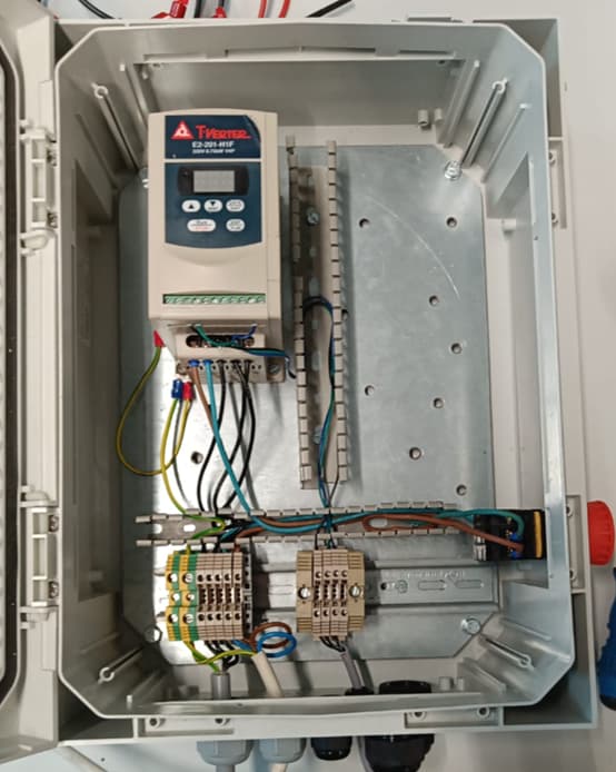
3b. Option B — control from an Arduino via a relay (T-verter E2-201-H1F)
Used when you want an Arduino (instead of a robot) to start/stop the belt.
-
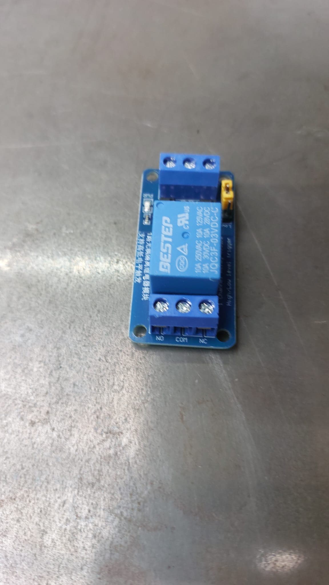
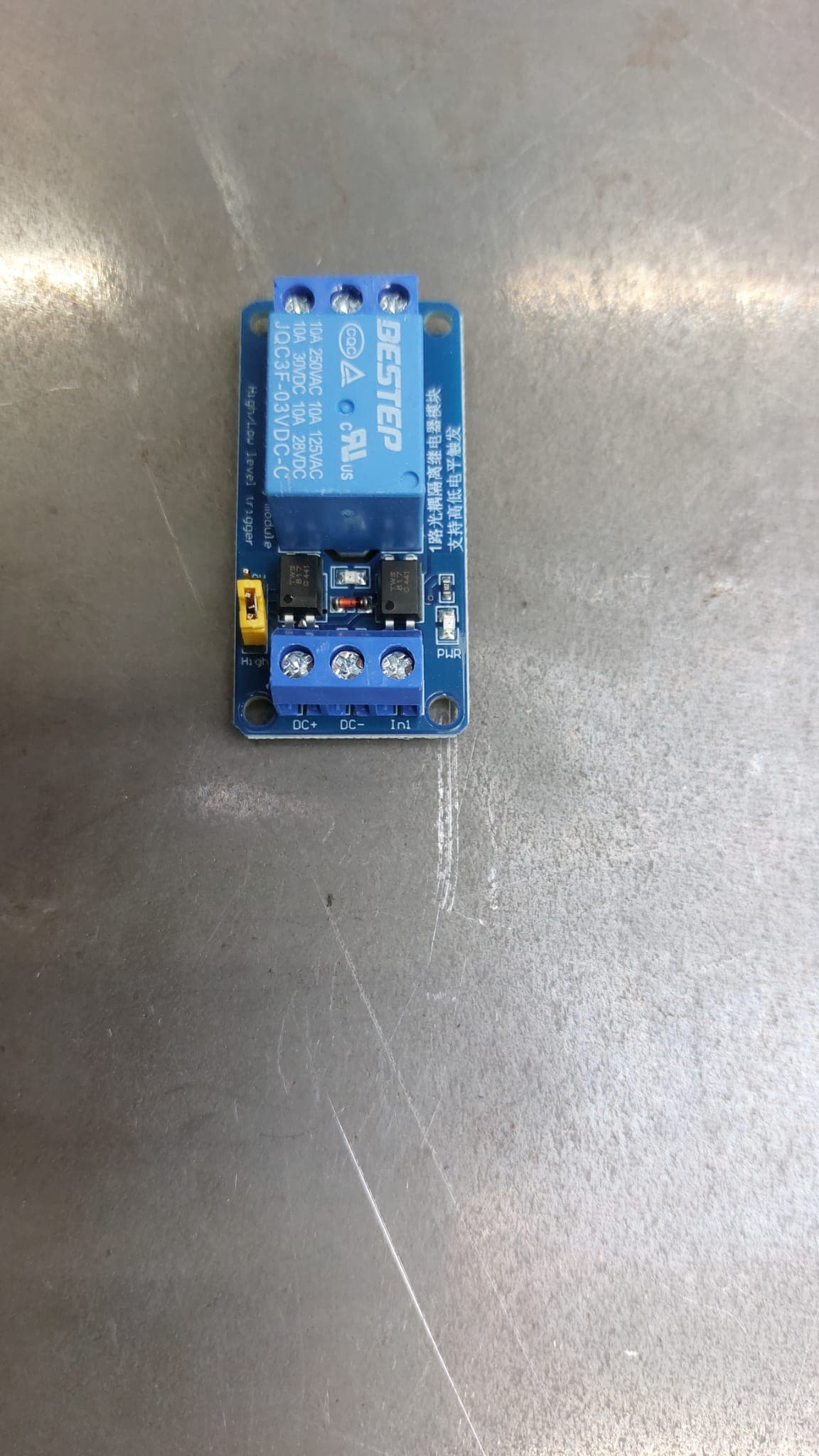
Wire a relay (JQC3F-03VDC-C) between the Arduino and the inverter’s input:
- Converter’s red wire → relay NO (normally open)
- Converter’s black wire → relay NC (normally closed)
- Relay COM → 24 V
-
On the Arduino side:
- Signal/input wire → the relay’s
Initerminal - Arduino GND → relay
DC- - Arduino 5V → relay
DC+
- Signal/input wire → the relay’s
-
Control the relay (and therefore the belt) from your Arduino code by driving the signal pin high/low.
-
Set F01 for the conveyor’s speed, F04 for direction, and F10 to enable Arduino/external control.

Related
- How to wire a conveyor belt’s electrical box (frequency inverter, E-stop, direction control) — general conveyor electrical box wiring
- How to calculate motor power, RPM and torque for a conveyor belt — how to size the motor for your conveyor
- How to control a conveyor belt over Modbus-RTU from Python (Mitsubishi FR-D720S inverter) — an alternative software control method (Modbus-RTU) for a different inverter model
Rewritten and consolidated (Sept 2026) from the original student how-to’s: How to setup the T-verter E2 220V inverter drive for use with a conveyor belt, Control a (conveyor) motor with a t-verter e2-201-h1f frequency converter.