Based on contributions by BryanSmit, DaanKlugt.
3D-printed parts fail or look bad more often because of design decisions than printer problems. This guide covers the design rules to follow while modelling in SolidWorks, and how to export a clean STL once the part is ready to print.
What you need
- SolidWorks (any recent version).
- A part you intend to 3D print, ideally on an FDM printer such as the How to print on the BambuLab P1S 3D printer in the robot lab.
Steps
1. Design for good bed adhesion
Give your part a large, flat bottom surface wherever possible — this gives the print plenty of bed contact and prevents the print from warping loose mid-print. A small contact area is a common cause of failed prints.
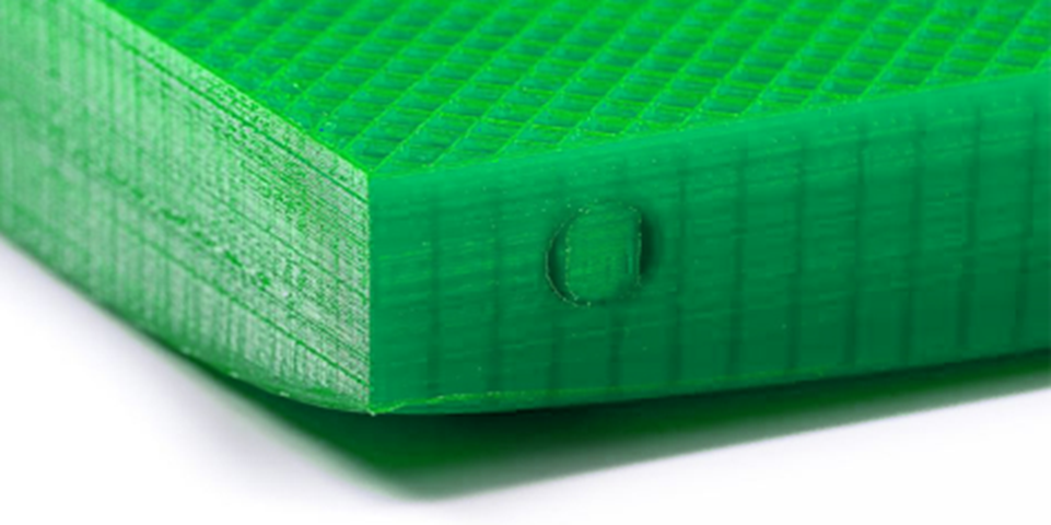
If you can’t avoid a small footprint, you can compensate with bed-adhesion aids (e.g. glue stick, adhesion sheets) or slicer features like brims or rafts — but rafts and brims often reduce surface quality on the affected faces, so treat them as a fallback rather than a default.
2. Chamfer the bottom edge to avoid elephant’s foot
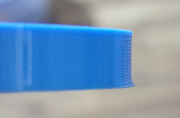
Not every printer is calibrated perfectly. A common artifact is “elephant’s foot”: the first layer gets squished too much and bulges outward. Design around it by adding a small chamfer on the bottom edge of the part — around 0.4 mm works well, compensating for roughly the first two layers.
3. Design to avoid support material
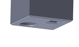
Supports leave visible witness marks because a small gap is needed between the support and the part (otherwise they fuse together). Where possible, design the part so it doesn’t need them:
- Keep overhangs at 45° or less from vertical (some printers can handle steeper angles — 45° is a safe default).
- Use bridging to your advantage: a straight, unsupported span that’s anchored on both ends can print fine even though it’s “in mid-air.” You can force a bridge next to a feature that would otherwise need support — for example, adding small 0.2 mm-increment cutouts next to a countersunk hole so the printer bridges across it instead of drooping into it.
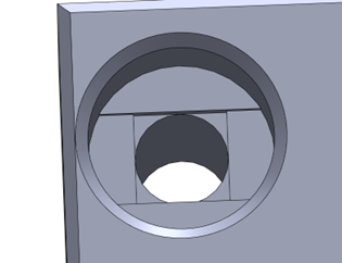
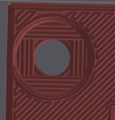
If supports really are unavoidable, consider modelling your own small support tabs directly into the part instead of relying on the slicer’s automatic supports — you use less material and get a support structure shaped exactly the way you want it removed.
4. Split large parts into modules
3D printing has a fast turnaround for iteration but is slow per print. If a multi-hour print turns out to have one dimension slightly wrong, you lose the whole print. Split large or unproven designs into smaller parts, so a single mistake only costs you a reprint of that one piece.
5. Add hardware for strength and precision
3D-printed parts are anisotropic — they’re noticeably weaker along the layer lines than within a layer. If a part needs to be strong, reinforce it with hardware: bolts add stiffness, and nuts or threaded inserts give you a solid connection point instead of relying on printed threads.
3D printing also isn’t very accurate — tolerances tighter than about 0.1 mm are essentially unreachable even on a well-calibrated printer. For connections that need tight tolerances, use hardware designed for it (bearings, dowel pins, bushings) rather than trying to print the fit directly.
6. Apply the standard 3D-print design rules
While modelling, keep these SolidWorks-specific guidelines in mind:
- Wall thickness: at least 1–2 mm for structural integrity.
- Clearances: leave a 0.2–0.5 mm gap between parts that need to slide or fit together — don’t design mating parts at exactly the same nominal size.
- Overhangs: keep below 45° where possible (see step 3).
- Holes for fasteners: add them during modelling using the Hole Wizard, so you get the correct diameter for your bolt size.
- Alignment features: add slots or alignment pins on parts that need to be assembled together, so they self-locate correctly.
7. Export the part as an STL
-
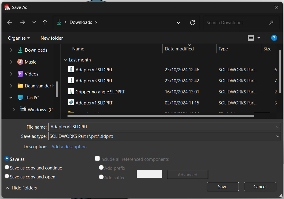
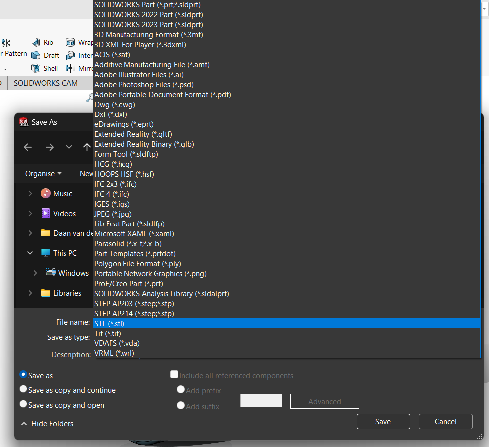
Go to File > Save As, and choose STL as the file type.
-
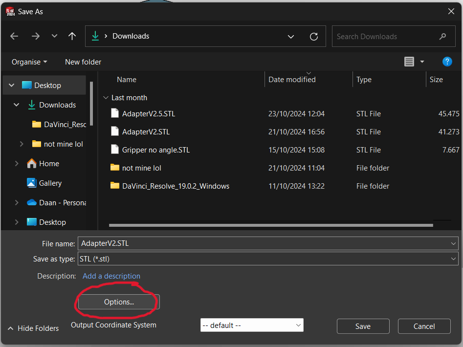
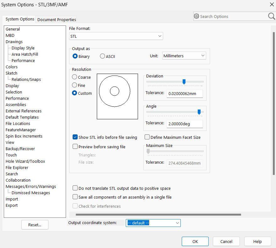
Click Options next to the file type to open the STL export settings.
8. Set deviation and angle for the mesh
The STL options let you control how closely the triangulated mesh follows the real curved surfaces, using Deviation and Angle:
- Deviation: the maximum distance allowed between the STL triangles and the true surface. Lower values give a smoother surface but a larger file.
- Angle: the angular tolerance between adjacent triangles, which also affects curve smoothness.
Guidelines:
- High-detail prints: low deviation (0.01–0.05 mm) and angle (5–10°).
- Simpler parts: higher deviation (0.1 mm) and angle (15°) — smaller file, faster slicing, no visible quality loss on parts without fine curved detail.
9. Save, check, and print
Confirm the settings and save the STL. Open it in your slicer (e.g. Bambu Studio, Cura, PrusaSlicer) to check for mesh issues before printing — most slicers let you preview the layers so you can catch problems before committing to a print. For printing on the lab’s printer, see How to print on the BambuLab P1S 3D printer in the robot lab.
Common mistakes
- Designing a part with a tiny footprint and no chamfer — expect warping and elephant’s foot.
- Sizing a fit exactly to nominal dimensions instead of leaving a 0.2–0.5 mm clearance — parts won’t slide or assemble.
- Relying on printed threads or tight tolerances for critical connections instead of adding hardware.
- Using a very coarse STL deviation/angle on a part with important curved features, then wondering why the print looks faceted.
Related
- How to print on the BambuLab P1S 3D printer in the robot lab
- How to model a 3D-printed press-fit bearing mount (intermediate parametric CAD tutorial)
Rewritten and consolidated (Sept 2026) from the original student how-to’s: How to optimize designing functional parts for 3D printing, How to Design Parts to 3D Print Using SolidWorks.