Based on contributions by sarahstam, Jeppe.
Stepper motors need a driver board between the controller and the motor coils. This guide covers two common setups used in the lab — a CNC shield with an Arduino Nano, and a standalone microstep driver wired to a Raspberry Pi or Arduino — plus what to consider when the stepper drives a geared mechanism instead of moving freely.
What you need
- A stepper motor (e.g. a NEMA 17)
- A multimeter, to identify the motor’s coil pairs
- Option A: CNC Shield V4, a TMC2209 motor driver module, an Arduino Nano, a stepper motor extension cable, a 12V AC-DC adapter
- Option B: a microstep driver (e.g. TB6600 or DM542), a Raspberry Pi (or another microcontroller that can output digital signals), a logic power supply (e.g. 3.3V), and a separate motor power supply (e.g. 9-24V, sized for your driver and motor)
Steps
1. Identify the coil pairs
Stepper motors have two coils (“spools”), each with two wires. A common wiring convention is coil 1 on pins 1 and 3 and coil 2 on pins 4 and 6, but this is not guaranteed for every motor. Check continuity between wire pairs with a multimeter before wiring anything up.
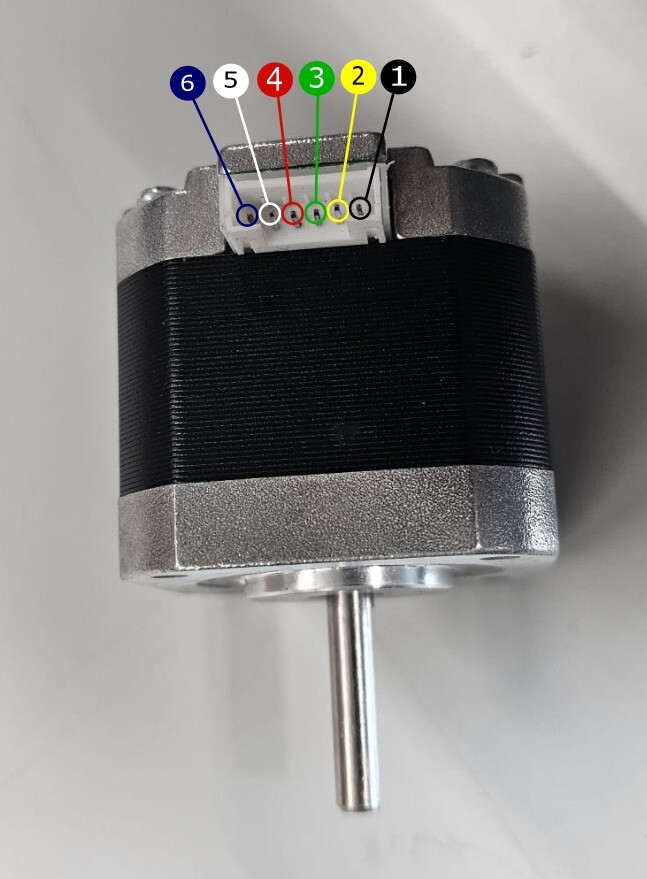
2. Option A — CNC shield with an Arduino Nano
Mount the Arduino Nano and the motor driver onto the CNC shield, then connect the stepper motor to the shield with the extension cable. Connect the Arduino to your computer over USB, but do not plug in the 12V adapter until the motor driver is correctly seated — plugging in power with the driver misaligned can damage it.
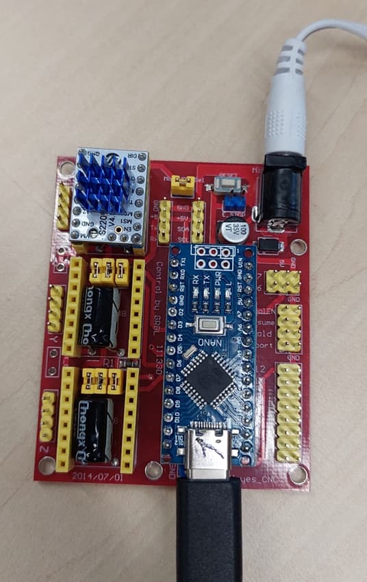
Once everything is wired, upload this sketch, which uses the AccelStepper library to move the motor a given number of steps on command:
#include <AccelStepper.h>

// Define the pins for your stepper motor
#define X_STEP_PIN 5
#define X_DIR_PIN 2
#define X_ENABLE_PIN 8

uint64_t last_message_time = 0;

// Create an instance of AccelStepper with DRIVER mode (step/direction control)
AccelStepper stepper(AccelStepper::DRIVER, X_STEP_PIN, X_DIR_PIN);

void setup() {
    Serial.begin(115200);
    Serial.setTimeout(10);
    pinMode(X_ENABLE_PIN, OUTPUT);
    delay(1000);
    stepper.setMaxSpeed(500);       // Maximum speed (steps per second)
    stepper.setAcceleration(5000);  // Acceleration (steps per second^2)
}

void loop() {
    if (Serial.available() > 0) {
        // Read the number of steps from the serial input
        long steps = Serial.parseInt();
        last_message_time = millis();

        if (steps != 0) {
            // Move the stepper by the given number of steps
            stepper.move(steps);
            stepper.runToPosition();  // Block until the move is completed
            delay(1);
            Serial.println("Done");
        }
    }
    // Disable the driver after 10 seconds of inactivity to save power / reduce heat
    if (millis() - last_message_time > 10 * 1000) {
        digitalWrite(X_ENABLE_PIN, HIGH);
    }
}
After uploading, open the Serial Monitor and type a number of steps. A positive number rotates the motor one way, a negative number rotates it the other way.
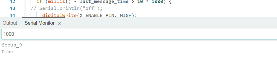
Check: the source sketch enabled/disabled the driver via
X_ENABLE_PINbut never set that pin toOUTPUT, and contained an unreachable duplicate check forsteps == 0inside thesteps != 0branch. Both are fixed above (addedpinMode(X_ENABLE_PIN, OUTPUT), removed the dead check).
3. Option B — microstep driver with a Raspberry Pi
This example uses a TB6600/DM542-style microstep driver, wired directly to a Raspberry Pi’s GPIO pins.
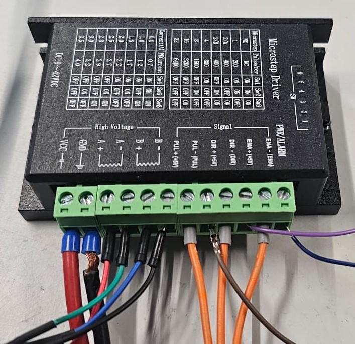

Use a separate power supply for the driver’s motor output (e.g. 9-24V, check your driver and motor ratings) — don’t power the motor from the Pi’s own 3.3V/5V rail, since the current draw can spike well above what the Pi can safely supply.
from time import sleep
import gpiozero

ENE = gpiozero.DigitalOutputDevice(22)  # Enable (High = enabled, Low = disabled)
DIR = gpiozero.DigitalOutputDevice(27)  # Direction (High = default, Low = reversed)
PUL = gpiozero.DigitalOutputDevice(17)  # Step pulse

delay = 0.0000015  # Delay between pulses - sets the motor speed
cycles = 1000       # Number of forward/backward cycles to run


def forward(duration):
    ENE.on()
    DIR.off()
    for _ in range(duration):
        PUL.on()
        sleep(delay)
        PUL.off()
        sleep(delay)
    ENE.off()
    sleep(0.5)  # Pause before a possible direction change


def backward(duration):
    ENE.on()
    DIR.on()
    for _ in range(duration):
        PUL.on()
        sleep(delay)
        PUL.off()
        sleep(delay)
    ENE.off()
    sleep(0.5)  # Pause before a possible direction change


if __name__ == "__main__":
    steps_per_cycle = 2000  # How many pulses per forward/backward move
    for cyclecount in range(1, cycles + 1):
        forward(steps_per_cycle)
        backward(steps_per_cycle)
        print(f"Cycles completed: {cyclecount}, remaining: {cycles - cyclecount}")
forward()/reverse()with no arguments (the functions were defined with adurationargument, andreversedidn’t exist — onlybackwarddid) and declaredforward/backwardwith a strayselfparameter outside of a class. The version above fixes all three issues.
4. Mechanical/gearing considerations for a geared assembly
If the stepper is driving something through gearing (pulleys and belts, a gearbox, a rotary table, etc.) rather than turning freely, keep in mind:
- Stepper motors are powerful for their size but have limited torque. Size your gearing ratio around the inertia and load of your mechanism, not just the desired speed.
- Reducing the step rate in software slows the motor down but does not increase torque — only mechanical gearing (or a different, higher-torque motor) does.
- Example: a heavy rotary table that didn’t need much speed used a 32:1 total gearing ratio.
For the electrical side of a geared setup with a NEMA 17 and a DM542 driver, the wiring is:
| Driver side | Stepper side |
|---|---|
| A+ | Black |
| A- | Green |
| B+ | Blue |
| B- | Red |
| Driver side | Arduino Uno side |
|---|---|
| PUL+ | Digital pin (e.g. pin 9) |
| PUL- | GND |
| DIR+ | Digital pin (e.g. pin 8) |
| DIR- | GND |
The driver needs its own external power supply (e.g. 24VDC) connected to V+ and GND — separate from the logic-level pins above.
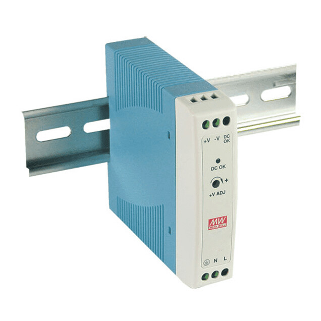
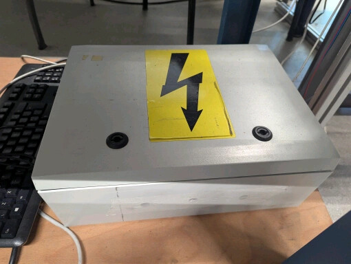
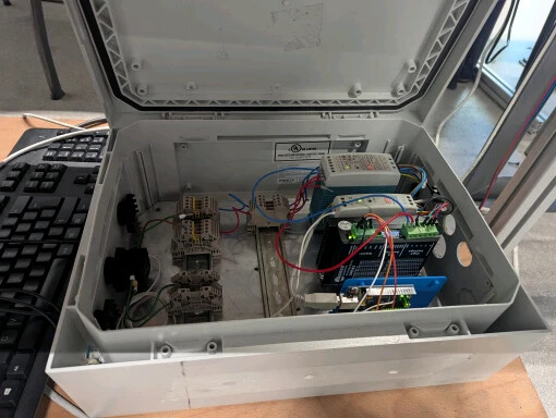
For a secure, safe setup, mount the driver, PSU, and related components on DIN rails inside an electrical cabinet — see How to build an electric safety box for components above 25V for how to build one.
DEG: 360(rotate a given number of degrees) andROTATE. If you need a full example, adapt the CNC-shield sketch in step 2, which already accepts a step count over serial.
Related
- How to build an electric safety box for components above 25V — building an electric safety box
- How to communicate between a Raspberry Pi and an Arduino over serial — communicating between a Raspberry Pi and an Arduino over serial
Rewritten and consolidated (Sept 2026) from the original student how-to’s: How to program a stepper motor, Arduino controlled stepper motor in geared assembly.